


21
5. A readily accessible, design-certified, manual oil shutoff valve, with a non-displaceable rotor
member, shall be installed in the fuel oil supply piping within 6 feet of the appliance.
6. A pipe union, or flanged connection, shall be provided downstream from the manual oil shutoff
valve to permit removal of the appliance oil pump. Pipe unions must be the ground joint type or
flanged-jointed using a gasket resistant to the corrosive action of fuel oils.
7. Pipe dope or thread sealant design-certified to be resistant to the action of fuel oils should be
used on all threaded joints. Thread sealant should only be applied to the male member of a
joint. The first two threads on the end of the male member of each pipe joint should be clean
and free from thread sealant.
8. Connection of the oil supply piping to the appliance should be made from the left-hand side of
the burner, facing the burner compartment cover.
9. When tubing is to be used for fuel oil supply lines, use of continuous runs of heavy wall copper
tubing is recommended. Avoid running tubing against any type of heating unit and across
ceiling or floor joists. If possible, install the tubing under the floor.
10. Where tubing is used for fuel oil supply lines, insure the tubing contains no kinks, sharp bends,
or collapsed regions where the inside cross-sectional area of the tube is greatly reduced. These
will excessively reduce the flow of oil.
11. Flared fittings should be used at all tube joints, when tubing is used for fuel supply lines. Do
not use compression fittings. Avoid the use of tube fittings in inaccessible locations.
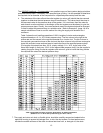
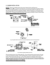
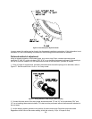
Burners are equipped with a single-stage, fuel pump. This type of fuel pump, when connected with a
supply line only, is satisfactory where the fuel supply is level with, or above the burner thus permitting
gravity flow of oil to the burner. If the tank is above the burner, and gravity oil feed to the burner is
permitted, a single line system may be used. The line should have a gradual slope downward of
approximately 1/2 inch per foot, or more, from the tank to a point directly below where it is connected to
the pump. Pitching the line upward toward the tank will help prevent the formation of air pockets in the
line.
NOTICE: An oil safety valve or a delayed-action, solenoid valve should be
installed in the oil supply line of all gravity-fed systems.
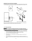
When the oil tank is located below the level of the burner, it is necessary to “lift” the oil to the burner. A
return line should be connected between the fuel pump and tank. This requires insertion of the "by-pass"
plug into the fuel pump. If the lift (vertical distance between the supply line inlet and the burner) exceeds
approximately 8 feet, a two-stage pump should be installed with a return line. When a return line is used
with either single or two-stage pumps, in-line air is automatically returned to the tank, making the oil pump
and lines self-purging.
Underground tanks should be located outside the building. Installation of above ground tanks is permitted
inside buildings, under certain conditions, as well as outside. Consult the Standard for Installation of Oil-
Burning Equipment for restrictions. If permitted, connect the burner oil supply line near the base of the
tank, opposite of the fill end. Connection at this point tends to flush older oil through and out of the tank.
This helps to prevent the accumulation of rainwater and condensed water vapor in the tank, which can
cause the tank to corrode.
If the oil supplier does not already use oil additives, it is recommended that additives be used to emulsify
any water accumulation in the oil.