


17
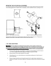
G. BURNER INSTALLATION:
NOTICE:
Remove all cardboard packing from around chamber before installing burner.
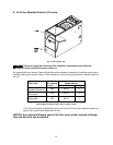
The oil burner will mount on three stud mounting bolts on the lower mounting plate covering the opening
in the front of the heat exchanger. The end of the burner tube should be inserted no further than 1/4 inch
back from the inside surface of the combustion chamber. A distance further than 1/4 inch back from the
inside chamber wall may cause impingement and sooting. This unit is equipped with a chamber retainer
(refer to Fig.12). The retainer secures the chamber during shipping and helps to maintain insertion depth.
DO NOT remove this retainer when installing burner.
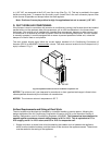
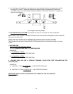
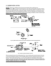
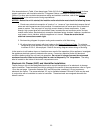
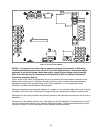
Fig. 12: Typical location of the over fire air tap and components in burner mounting plate area
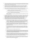
Fig. 13: Burner insertion illustration (Top view)
When mounting the burner, the mounting plate (Fig. 12) must be removed to provide access to the area
in front of the combustion chamber. A fiber insulating sleeve or amulet is provided on the burner tube of
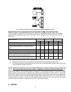
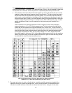
specific Thermo Pride burners.(see Fig. 13). See Thermo Pride burner application chart for type of
insulator. Do not allow the burner tube or end cone to physically touch or protrude into the chamber, as
excess heat transfer could result in destruction of the tube, end cone or both. The burner tube/end cone is
properly positioned, when the end is ¼ inch back from the inside surface of the combustion chamber wall.
DO NOT CHANGE POSITION OF THE CHAMBER!