


All installations and services must be performed by qualified service personnel.
2
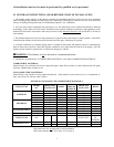
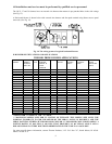
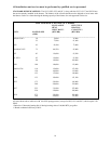
The minimum clearances listed in the preceding table are for fire protection. Clearance for servicing the front of the
furnace and the rear of the lowboy models should be at least 24 inches. A clearance of 24 inches is recommended
for passage to all points on the furnace requiring service access.
The OH2-3-5-11-16 furnaces may be installed on combustible flooring. The OL2-5-11-16-20-33-37-39 and OC2-5
furnaces are to be installed on non-combustible flooring only. A non-combustible floor base is available for the
counterflow models OC2-5, which then allows these models to be adapted for installation on combustible flooring
(use non-combustible floor base Model No.125 for OC5, Model No 56 for OC2).
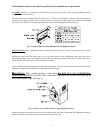
NOTE: The OH2 furnace is approved for closet installation. If the OH2 is installed in a closet, it requires two
openings in the closet door for combustion air, each having a minimum area of 162 sq. inches. This free area for the
OH2 intentionally exceeds the recommended minimum free area of 2 square inches per 1000 BTUH of input rate.
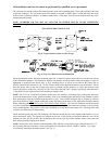
NOTE: When power venting a Thermo Pride oil fired furnace with a power venting system other than the system
supplied by Thermo Pride, a fiber chamber and an isolated combustion air kit (PVB or Beckett boot) is to be used
with the other manufacturers power venting system.
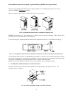
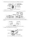
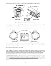
NOTE: On the front flue, lowboy, all highboy or counterflow models, it is possible to rotate the flue elbow (which is
factory installed for vertical discharge) 90°
counterclockwise from the vertical position to adapt to various venting
systems. (See following page for details)
?
??
? CAUTION MUST BE TAKEN NOT TO EXCEED 90° ROTATION (OF THE FLUE
ELBOW) COUNTERCLOCKWISE OR RIGHT FROM THE VERTICAL POSITION.
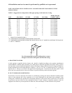
ROTATION OF FRONT FLUE ELBOW
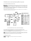
When an installation requires that the flue exit out the left hand side casing on a front flue unit, remove screw
securing the 90 deg. elbow and rotate it 90° counterclockwise.
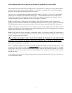
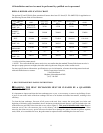
Then, by following dimensions in Table 1, locate the
center point for the exit of the flue for the particular size furnace. Once the center has been located, use a scribe to
mark the hole size, listed in the chart, which corresponds with the furnace being used. Cut hole out and extend flue
through side casing.
A trim collar may be ordered from Thermo Products to hide the gap around the flue pipe. This trim collar, however,
is not required for operation.