


All installations and services must be performed by qualified service personnel.
1
II. GENERAL INSTRUCTIONS - READ BEFORE START OF INSTALLATION
1. The heating output capacity of the furnace proposed for installation should be based on a heat loss calculation
made according to the manuals provided by the Air Conditioning Contractors of America (ACCA) or the American
Society of Heating, Refrigeration and Air Conditioning Engineers, Inc. (ASHRAE).
2. All local codes and/or regulations take precedence over the instructions in this manual and should be followed
accordingly. In the absence of local codes, installation must conform with these instructions and regulations of the
National Fire Protection Association, and to the provisions of the National Electrical Code
(ANSI/NFPA 70-1999 or
latest edition).
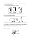
3. The installed furnace must be level and positioned in a central location with respect to outlet registers. It should be
located near the chimney to minimize any horizontal run of flue pipe, which may be required.
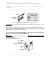
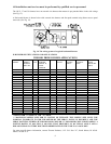
4. A furnace installed in a residential garage must be installed so the burner and ignition source are located higher
than 18 inches above the floor, unless the required combustion air is taken from the exterior of the garage. Also, the
furnace must be located or protected to avoid physical damage by vehicles.
?
??
?WARNING: This furnace is not to be used as a construction heater.
5. Listed below are definitions of "COMBUSTIBLE MATERIAL" and "NON-COMBUSTIBLE MATERIAL."
COMBUSTIBLE MATERIAL:
Material made of or surfaced with wood, compressed paper, plant fibers, plastics, or other material that will ignite
and burn, whether flame resistant or not.
NON-COMBUSTIBLE MATERIAL:
Material that is not capable of being ignited and burned. Such materials consist entirely of, or a combination of,
steel, iron, brick, tile, concrete, slate, or glass.
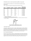
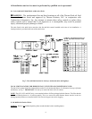
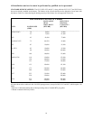
MINIMUM CLEARANCES TO COMBUSTIBLE MATERIALS
TYPE OF UNIT
MODEL
NO.
1
FROM SIDES
OF FURNACE
FRONT
TOP &
SIDES OF
PLENUM
FROM THE
FLUE/VENT
REAR
OL2 1” 2” 1” 4” 1”
OL5,11,16 1” 24” 1” 6” 1”
OL20 1” 24” 1” 18” 1”
LOWBOYS
OL33,37,39 1” 24” 1” 18” 1”
OH3,11 1” 24” 1” 9” 1”
OH5 1” 24” 1” 6” 1”
OH16 1” 24” 1” 9” 1”
HIGHBOYS
OH2 1” Note
3
2” 9” 1”
OC2 1” 4” 1” 6” 1”
COUNTERFLOWS
OC5 1” 4” 1” 9” 1”
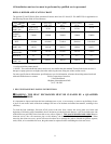
TYPE OF UNIT
MODEL
NO.
1
FRONT TOP REAR BOTTOM FROM THE
FLUE/VENT
ANY SIDE
OF
PLENUM
OT5 24” 1” 1” 1” 4” 1”
HORIZONTALS
2
OT11,16 24” 1” 1” 1” 9” 1”
Notes:
1
The above are abbreviated model numbers.
2
Horizontal units are not approved for attic installation.
3
OH2 front clearance for 6” for Closet, 18” for Alcove.