


19
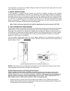
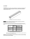
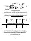
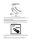
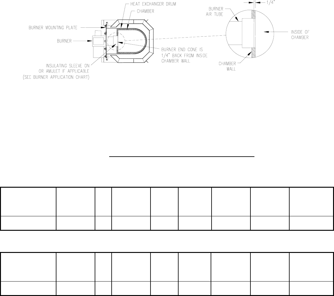
Fig. 13: Burner insertion illustration (Top view)
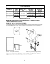
When mounting the burner, the mounting plate (Fig. 12) must be removed to provide access to the area
in front of the combustion chamber. A fiber insulating sleeve or amulet is provided on the burner tube of
specific Thermo Pride burners.(see Fig. 13). See Thermo Pride burner application chart for type of
insulator. Do not allow the burner tube or end cone to physically touch or protrude into the chamber, as
excess heat transfer could result in destruction of the tube, end cone or both. The burner tube/end cone is
properly positioned, when the end is ¼ inch back from the inside surface of the combustion chamber wall.
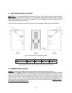
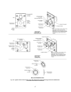
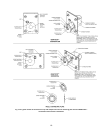
For horizontal applications, the mounting plate and chamber retainer will need be rotated 90º left or right,
depending on furnace position. DO NOT CHANGE POSITION OF THE CHAMBER!
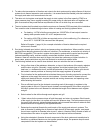
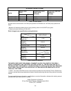
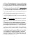
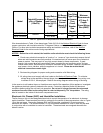
H. BURNER SPECIFICATIONS AND APPLICATIONS:
FURNACE MODEL
THERMO
PRIDE’S
BURNER
SPEC NO.
*
INS
BECKETT
BURNER
MODEL &
TUBE
LENGTH
HEAD STATIC
PLATE
MAXIMUM
NOZZLE
SIZE**
SHIPPED
NOZZLE SIZE
OIL
PUMP
PRESSURE
(PSIG)
OD6**072D**B TP2501 N AFG-4.5” F3 3-5/8
0.75X80° H 0.60X80° H
120
The optional BF3 Riello flame retention oil burner can be used with OH6.
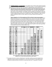
FURNACE MODEL
THERMO
PRIDE’S
BURNER
SPEC NO.
*
INS
RIELLO
BURNER
MODEL &
TUBE
LENGTH
HEAD STATIC
PLATE
MAXIMUM
NOZZLE
SIZE**
SHIPPED
NOZZLE SIZE
OIL
PUMP
PRESSURE
(PSIG)
OD6**072D**R C8511325 S BF3-4.5” N/A N/A
0.70X80° H 0.60X80° H
140
Table 6: Beckett & Riello burners specifications
* INSULATOR S = SLEEVE OR N = NONE
THE NOZZLE SIZE GIVES THE NOMINAL FLOWRATE, IN GPH, FOLLOWED BY THE SPRAY
ANGLE, IN DEGREE’S, AND THE SPRAY PATTERN, EITHER “H” FOR HOLLOW CONE OR “S”
FOR SOLID CONE. FOR EXAMPLE, A NOZZLE RATED AT 0.65 GPH @ 100 PSIG THAT PROVIDES
AN 80° SPRAY ANGLE AND A HOLLOW SPRAY PATTERN WOULD BE ABBREVIATED IN THE
TABLE AS “0.65 X 80°H”.
For more specific burner information, contact:
Thermo Products, LLC. P.O. Box 217, North Judson, IN 46366.
Phone 574-896-2133.