


14
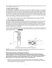
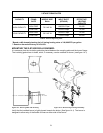
8. As a final step in the installation, the appliance must be adjusted to deliver a temperature rise within
the range of 50° to 80°F. Adjust the blower motor speed to obtain a temperature rise within the
acceptable range. The required blower speed will depend on the airflow resistance of a supply and
return air duct systems.
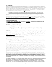
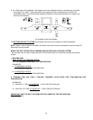
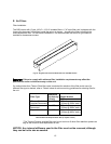
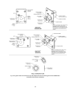
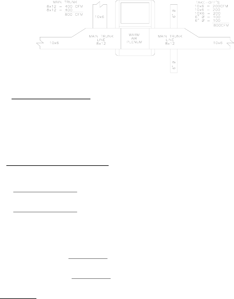
Fig. 9: Supply air duct sizing Example
The RETURN AIR DUCT SYSTEM
should equal the warm air duct system in airflow capabilities.
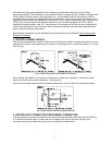
NOTE: When a return register is located in the same room as the furnace, the register must be at least 20
feet away from the furnace.
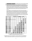
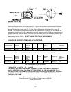
SIZING THE DUCT WORK FOR A COMBINATION HEATING AND COOLING SYSTEM:
Two formulas must be used in determining the CFM requirements of a combustion heating and cooling
system.
1. HEATING CFM:
HEAT OUTPUT OF FURNACE (BTUH)
1.1 X TR (TEMPERATURE RISE, °F) = HEATING(CFM)
EXAMPLES:
A. 110,000 BTUH OUTPUT
1.1 X 85°F TR = 1176 CFM FOR HEATING
B. 110,000 BTUH OUTPUT
1.1 X 70°F TR = 1429 CFM FOR HEATING
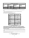
2. COOLING CFM: 400 CFM X COOLING TONNAGE (12,000 BTUH PER TON)=AIRFLOW FOR
COOLING(CFM)
EXAMPLES:
A. 400 CFM X 3 TON (12,000 BTUH)
= 1,200 CFM FOR COOLING
1TON
B. 400 CFM X 2.5 TON (12,000 BTUH)
= 1,000 CFM FOR COOLING
1 TON
IMPORTANT:
SIZE THE DUCT SYSTEM FOR THE LARGER OF THE TWO AIRFLOW
REQUIREMENTS.