


35
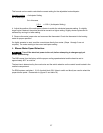
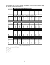
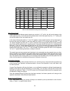
DIP SWITCH 2 SECTION STATE
BLOWER DELAY TIMES
1 2 3 4
Counter Flow
ON - SEC
ON - SEC OFF - MIN
OFF OFF 15 30
ON OFF 24 60
OFF ON 36 120
ON ON 48 240
OFF OFF 2
ON OFF 4
OFF ON 6
ON ON 8
Table 11: ON and OFF Blower Delay Time Switch Settings
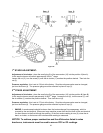
Motor Blower Speed
Three interconnected blower speed outputs are provided. A “G” call for fan will provide power to the
LOW speed tap only. A “W” heat call will provide power to the Heat speed tap only. A “Y” cooling call
will provide power to the Cool speed tap only.
In the case of thermostat calls for “Y” and “W” together, blower speed selection will be determined by
the input that was first initiated. In the case where the control is in a cooling mode with both “Y” and
“W” inputs energized and then the “Y” input is removed, the cooling blower off time will be executed
prior to the control switching into a heating mode. In the case where the control is in a heating mode
with both “Y” and “W” inputs energized and then the “W” input is removed, the heating blower off time
will be executed prior to the control switching into a cooling mode. In the case where a call for fan “G”
already exists and either a “W” or a “Y” call is initiated, the blower speed will switch to the respective
“W” or a “Y” speed following the blower on delay for that call.
The speed taps are interconnected and interlocked, only one speed may be powered at any one time.
When a speed is to be operated, the speed select relays are operated to select the path to the motor
tap and then the enable relay is operated to switch the operating power to the selected motor speed
tap. If the speed of the running motor is to be changed, first the enable relay removes power from the
motor, the new speed is selected and then power is restored to the motor.
Counterflow Operation
Counter flow operation will be allowed if JW10 is cut. If JW10 is not cut, the control will not perform any
of the Counter Flow Operation as described below. Counter Flow Operation is only valid when a call
for Heat is present.
Counter Flow Operation will bring the blower on at a defined low speed at a defined time between the
enabling of the burner and the selected turn on time delay. Turn on delay times for the Counter Flow
Operation are defined in Table 11. For PSC control, the LOW speed blower tap will be energized once
the selected on delay has expired.
Once the selected Blower On Delay time has been reached, the blower operation will change to the
operation described in Motor Blower Speed section.
Blower On and Off Delays
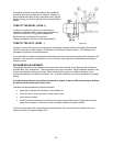
Four Heat blower on and four blower off delays are selected by two dip switches for each function.
Refer to Table 11 for specific delay values.