


24
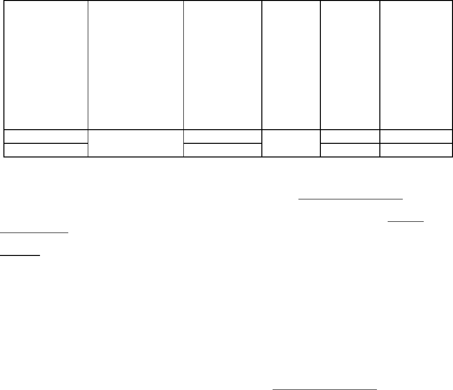
Model
Potential/Frequenc
y/No. of Phases
(V/Hz/Ph)
Supply/Return
A
ir Blower Full
Load Current
(Amps) @ 115
VAC
Oil Burner
Assembly
Full Load
Current
(Amps) @
115 VAC
Maximum
Time Delay
Type Fuse
or Inverse
Time
Circuit
Breaker
Size
(Amps)
Minimum
Recommende
d 75 deg. C.
Copper
Power Wiring
Size (AWG)
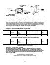
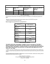
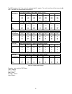
OD6**072D48 7.5 PSC 15 12
OD6**072DV5 10.1 ECM 15 12
1.7120/60/1
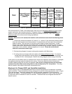
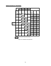
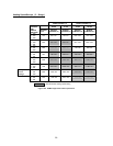
Table 10: Typical Electrical Requirements for Various OD6 Models
Wire size selections in Table 10 are based upon Table 310-16 of the National Electrical Code
for three
copper conductors, with insulation rated for 75 degrees Celsius, contained in raceway at 30 degrees
Celsius. For other wire insulation temperature ratings and ambient conditions, refer to the National
Electrical Code for the minimum wire sizing requirements.
NOTICE:
Before the unit is started, the installer and/or electrician must check the following items:
1. Check every electrical connection of “push-on” or “screw-on” type terminals to ensure that all
wires and wire connectors are firmly secured. A loose terminal can cause poor flow of electrical
power to motors. This may result in very high current draws by these components. If great
enough, high current draw will cause blown fuses, burned wires and contactor points, and pre-
mature motor failure. Each electrical connection has been factory checked, however, connections
may loosen, due to vibration, while the appliance is in transit. Please be certain that all
electrical connections remain tight.
2. Review wiring diagram for proper routing and connection of all field wiring.
3. All wiring sizes must comply with local codes or the National Electrical Code
. To minimize
voltage drop to the appliance, the next larger size wire should be used when long wiring runs,
in excess of 100 ft., are employed. Refer to the wiring diagrams when wiring or servicing.
In the event a circuit breaker trips or a fuse blows as a result of the operation of this appliance, investigate
the appliance electrical system to determine the cause. Correct any electrical faults and abnormal
conditions before putting the unit back into operation. Do not put in a larger fuse and do not exceed
maximum fuse size listed on the rating label in order to temporarily “fix” the problem. The rating
label is located on the inside of the burner compartment cover.
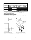
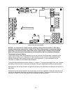
Electronic Air Cleaner (EAC) and Humidifier Installation:
The fan timer on this unit has designated terminals to control the operation of an electronic air cleaner
and/or humidifier. These terminals provide line voltage for the control of these accessories, refer to Figure
15 on the next page. Connection between EAC and N6 provides a switched 115 vac to power an
electronic fan cleaner. The same switched 115 vac is available between EAC and N7 and may be used
in conjunction with a humidistat to control a humidifier. These terminals are energized whenever the
blower is active.