


32
M. BLOWER CONTROLLER INFORMATION FOR PSC MOTOR
(Note: for ECM blower controller information see: ECM Operation Manual document # Mo-440)
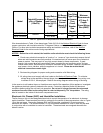
TERMINAL DEFINITIONS & FIELD WIRING
Burner Harness Connector P1
Pin 1- Limit switch connector.
Pin 2- 120 VAC Line connection.
Pin 3- Burner pilot contact.
Pin 4&5- 120 VAC Neutral connections.
Pin 6- Burner pilot contact.
Pin 7&8- From oil primary control.
Pin 9- Limit Switch Input (LSI).
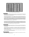
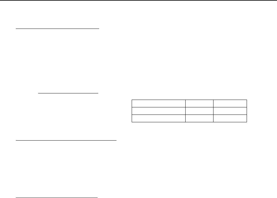
Field Wiring to Burner
Harness Wires
Beckett Connections
Riello Connections
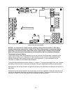
Thermostat / Humidistat connections
“C” Common / ground
“W” Thermostat call for heat
“R” 24 VAC to thermostat
“G” Thermostat call for fan
“Y” Thermostat call for cool
“DEHUM” Humidistat call for dehumidification (TXV systems ONLY)
Male quick connect terminals.
“S1-3” 120 VAC Hot
“N1-7” 120 VAC Neutral
“EAC” Electronic Air Cleaner (120 VAC) connection
“FAN” Fan On Signal
“X” 24 VAC from transformer
“C” 24 VAC common from transformer
“CC” Compressor Contactor
“CC_COM” Compressor Contactor Common
“LOW” Continuous Blower Speed
“HEAT” Blower heat speed tap
“COOL” Blower cool speed tap
Pilot (Tstat) Neutral Line
Yellow Wires White Red
T-T terminals White Black
T-stat terminals White Black