


All installations and services must be performed by qualified service personnel.
6
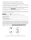
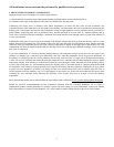
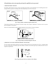
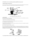
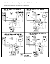
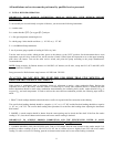
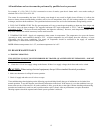
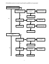
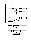
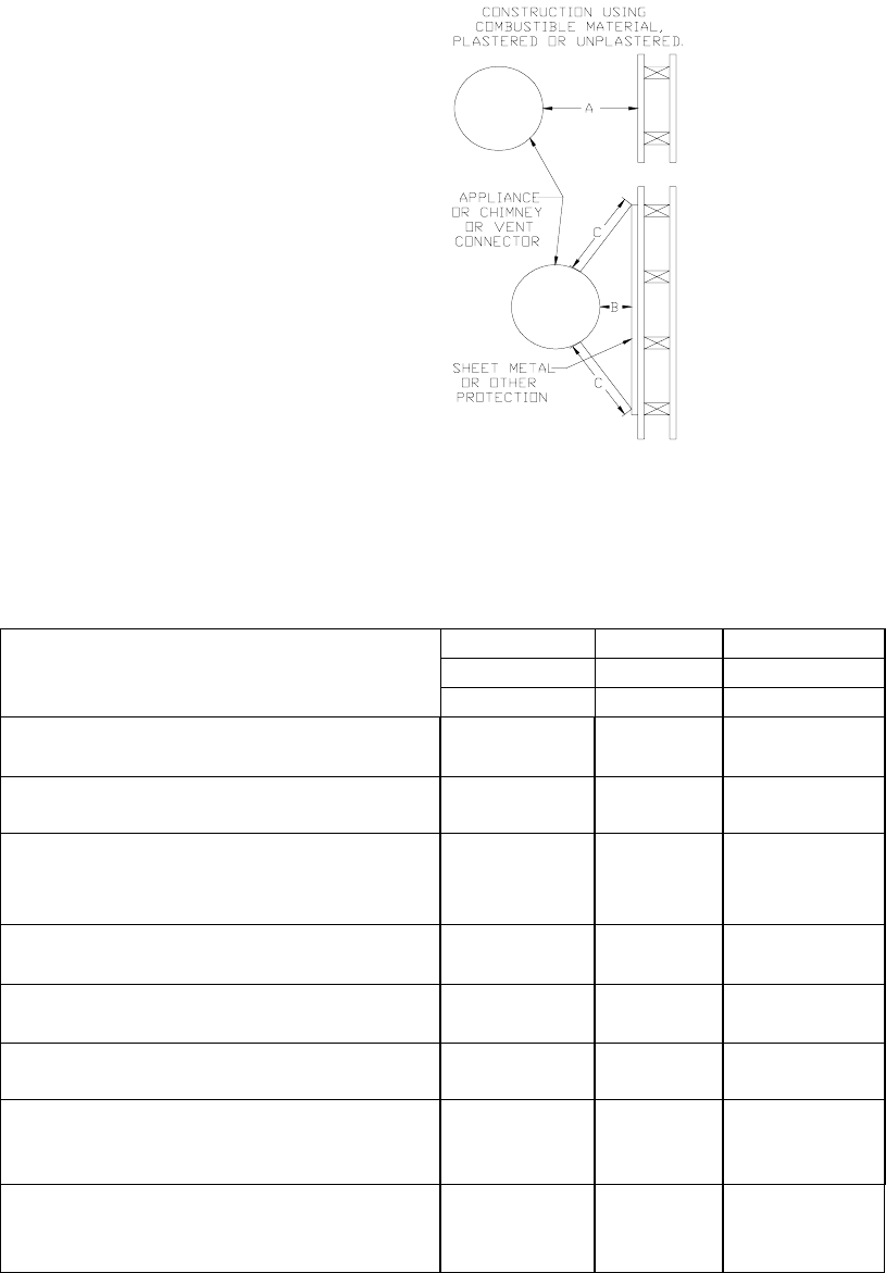
Fig. 7: Alternate constructions that allow reduced clearances to combustible materials.
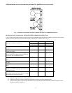
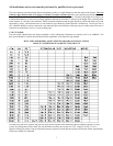
REDUCTION OF CLEARANCES WITH SPECIFIED FORMS OF PROTECTION
Type of protection applied to and covering all surfaces of combustible material within the distance specified as the required
clearance with no protection unless otherwise noted, all dimensions in inches, refer to Fig. 7.
18 inches 9 inches 6 inches
Sides & Sides & Sides &
Required clearance with no protection from the
appliance or chimney connector is:
Above Rear Above Rear Rear
a. 3-1/2" thick masonry wall without ventilation
air space….
-- 12 -- 6 -- 5
b. 1/2" insulation board over 1" glass fiber or
mineral wool batts…
12 9 6 5 4 3
c. 0.024(24 gauge) sheet metal over 1" glass
fiber or mineral wool batts reinforced with wire
on rear face with ventilated air space…
9 6 5 3 3 3
d. 3- 1/2" thick masonry wall with ventilation air
space..
-- 6 -- 6 -- 6
e. 0.024 (24 gauge) sheet metal with ventilated
air space.
9 6 5 3 3 2
f. 1/2" thick insulation board with ventilation air
space..
9 6 5 3 3 3
g. 0.024 ( 24 gauge) sheet metal with ventilated
air space over 0.024 (24 gauge) sheet metal with
ventilated air space….
9 6 5 3 3 3
h. 1" glass fiber or mineral wool batts
sandwiched between two sheets 0.024 (24 gauge)
sheet metal with ventilated air space
9 6 5 3 3 3
A. Equal the required clearance with no protection.
B. Equals the reduced clearance permitted in accordance with the preceding clearance chart.
C. The protection applied to the construction that covers the combustible material should extend far enough in each
direction to make C equal to A.