


All installations and services must be performed by qualified service personnel.
6
III. GENERAL INSTALLATION
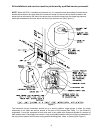
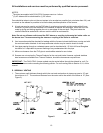
These Category Type IV furnaces are shipped completely assembled and wired (internally). See the
Dealer Receiving and Freight Claim Procedure
Section of the price guide for parts shortage or damage.
The furnace and duct system must be adjusted to obtain a temperature rise of 55°F to 85°F through the
furnace after installation. (See rating label located on side panel inside the furnace vestibule). The
installation must conform with local codes, or in the absence of local codes, with the National Fuel Gas
Codes (ANSI Z223.1 or latest edition) and with these instructions.
: This furnace is not to be used for temporary heating of buildings or structures under
construction.
Many of the chemicals used during construction, when burned, form acid bearing condensate that can
substantially reduce the life of the heat exchanger.
A. CODES AND CLEARANCES
The following items must be considered when choosing the size and location of the furnace.
1. All local codes and/or regulations take precedence over the instructions in this manual and should be
followed accordingly. In the absence of local codes, installation must conform with these instructions,
regulations of the National Fire Protection Association, provisions of National Electrical Code
(ANSI/NFPA70 or latest edition), and the National Fuel Gas Code
(ANSI Z223.1 or latest edition).
2. The BTU output capacity of the furnace proposed for installation should be based on a heat loss
calculation made according to the manuals provided by the Air Conditioning Contractors of America
(ACCA) or ASHRAE.
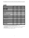
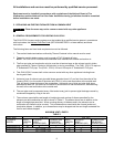
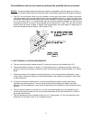
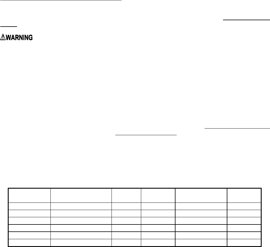
3. MINIMUM CLEARANCES TO COMBUSTIBLE MATERIALS
TABLE 1
MODEL NO.
FROM SIDES OF
FURNACE & REAR
FRONT
TOP OF
PLENUM
FROM THE
FLUE OR VENT
SIDE OF
PLENUM
CHX1-75
0 IN. 6 IN. 0 IN. 0 IN. 1 IN.
CHX1-100
0 IN. 6 IN. 0 IN. 0 IN. 1 IN.
CHX1-125
0 IN. 6 IN. 0 IN. 0 IN. 1 IN.
CDX1-75
0 IN. 6 IN. 0 IN. 0 IN. 1 IN.
CDX1-100
0 IN. 6 IN. 0 IN. 0 IN. 1 IN.
CDX1-125
0 IN. 6 IN. 0 IN. 0 IN. 1 IN.
The CHX1-75, 100 and 125 furnaces may be installed on combustible flooring. The furnace shall not be
installed directly on carpeting, tile or other combustible material other than wood flooring.
The CDX1-75, 100 and 125 furnaces are to be installed on non-combustible flooring only. The non-
combustible floor bases model no. 50 CA base for CDX1-75 model no. 100 CA base for the model no.
CDX1-100 and model no. 125 CA base for CDX1-125 are available for the counterflow furnaces to allow
their installations on combustible flooring.
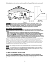
These furnaces may be installed in an alcove or in a closet if the minimum clearances to combustible
construction (listed previously) are met. The CDX1 series furnaces may be installed in an attic or crawl
space. Refer to section III, B1 of this installation manual.
The minimum clearances are listed for fire protection. Clearance for servicing the front of the furnaces and
to all points on the furnace requiring access must be 24”*.
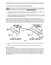
*For horizontal furnace installation, refer to section III, B1 of this installation manual.