


All installations and services must be performed by qualified personnel.
8
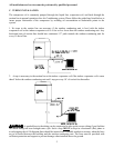
F. DUCT SYSTEM
The duct system and load sizing calculation should follow the design standards of Air Conditioning
Contractors of America (ACCA) - Manuals D&J -or the American Society of Heating, Refrigeration & Air
Conditioning Engineers, Inc. (ASHRAE) Fundamentals Volume (latest edition).
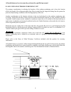
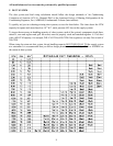
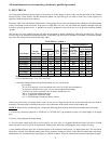
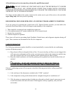
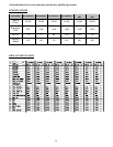
To quickly aid you in evaluating existing duct systems, review the chart below. The chart shows the CFM
capacity for square inch areas based on .10" W.C. static pressure (SP) loss on the supply systems.
To insure the necessary air handling capacity of a duct system, each of the system's components (trunk lines,
takeoff's, runs and register and grill free areas) must be properly sized and matched together. A 12x8 duct
with a 400 CFM capacity, for example, WILL NOT flow 400 CFM if the register(s) can only flow a total of
200 CFM.
When sizing the return air duct system, the air handling capacity MUST BE EQUAL TO the supply system
at a minimum. It is recommended that you follow design parameters established by ACCA or ASHRAE on
the return air duct systems.