


9
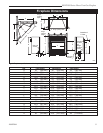
RDVDSN Series Direct Vent Gas Fireplace
20007894
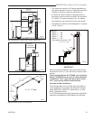
Your fireplace is approved to be vented either through
the side wall, or vertical through the roof.
• Only CFM Corporation venting components spe-
cifically approved and labelled for this fireplace
may be used.
• Venting terminals shall not be recessed into a wall or
siding.
• Horizontal venting which incorporates the twist lock
pipe must be installed on a level plane without an
inclining or declining slope.
• Horizontal venting which incorporates the use of flex
venting shall have an inclining slope from the unit of
1” (25 mm) per 24” (610 mm).
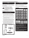
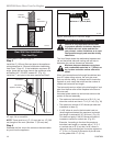
General Venting
There must not be any obstruction such as bushes,
garden sheds, fences, decks or utility buildings within
24” from the front of the termination hood.
Do not locate termination hood where excessive snow
or ice build up may occur. Be sure to check vent termi-
nation area after snow falls, and clear to prevent ac-
cidental blockage of venting system. When using snow
blowers, make sure snow is not directed towards vent
termination area.
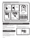
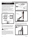
Location of Vent Termination
It is imperative the vent termination be located observ-
ing the minimum clearances as shown on the following
page.
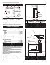
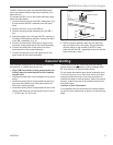
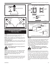
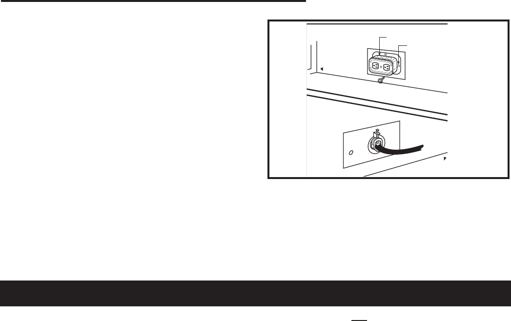
The EB-1 Electrical junction box has been fitted stand
-
ard on this model to allow for the easy connection of an
optional fan kit.
To connect the EB-1 box to the house electrical supply
follow the steps below.
1. Unscrew retaining screw from EB-1 base plate (Fig.
8) and remove the EB-1 assembly from the appli-
ance.
2. Remove the front cover of the EB box.
3. Remove the plug socket assembly from the EB-1
box.
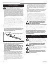
4. Feed the supply line in through the EB-1 opening in
the side of the appliance and then through the back
of the EB-1 assembly. (Fig. 6)
5. Connect the black wire of the power supply line to
the brass screw (polarized) of the socket assembly.
6. Connect the white wire of the power line to the
chrome screw of the socket assembly.
7. Connect the ground wire of the supply line to the
green screw of the socket assembly.
FP580
INSTA VENT FREE
EB1 JUNCTION BOX
11/18/97
OUTSIDE
FRONT OF UNIT
INSIDE
FRONT OF UNIT
Electrical Box
Retaining Screw
FP580
Fig. 6 EB-1 receptacle.
8. Refit the socket assembly back into the electrical
box and replace the cover plate. Secure the cable
with the clamp on the outside of the EB-1 base
plate and refit the EB-1 assembly to the unit with the
screw removed in step 1.