


28
RDVDSN Series Direct Vent Gas Fireplace
20007894
T207
air shutter
setting
1/8/04 djt
T207
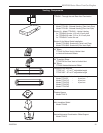
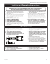
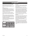
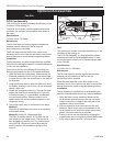
Fig. 49 Air shutter settings for propane/LP gas.
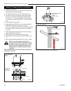
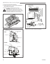
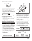
3/8” - All Models
Fig. 48 Replace burner orifice with correct conversion orifice.
T259
remove burner
orifice
6/04
Split Nut Assembly
Air Shutter
Burner Orifice
T259
2. Move burner tube back to original position, tighten
split nut assembly and bend tabs back up.
3. Set the air shutter opening for propane/LP gas. Tight-
en air shutter screw. (Refer to Figure 49 and Chart on
Page 31)
NOTE: Failure to adjust air shutter to proper setting
will produce sooting.
4. Fasten pilot to burner bracket with two (2) screws.
5. Replace grate assembly.
WARNING: Failure to position the parts in accor
-
dance with these diagrams or failure to use only
parts specifically approved with this heater may
result in property damage or personal injury.
Valve Conversion
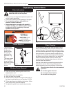
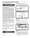
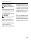
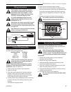
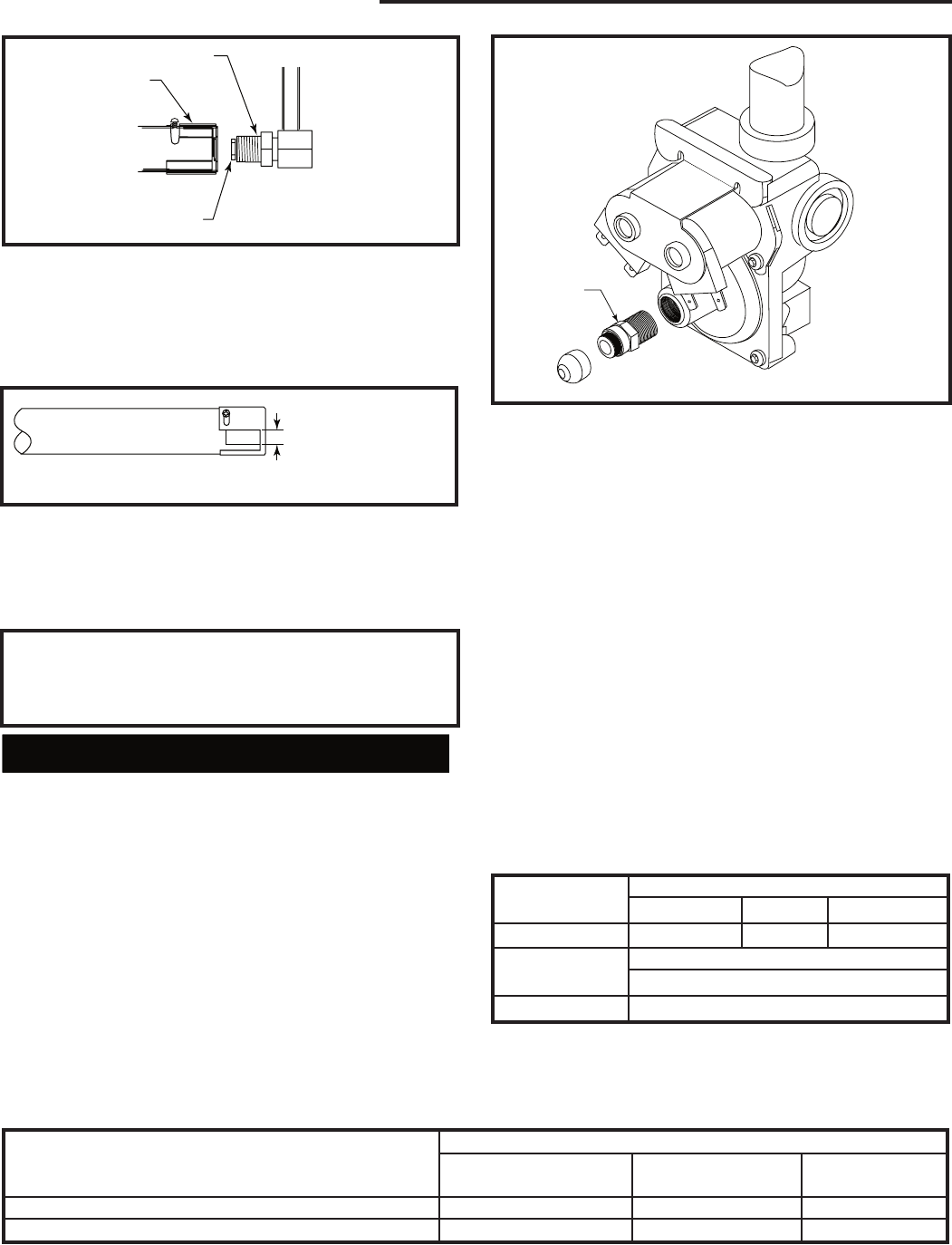
1. Remove plastic cap from regulator fitting. (Fig. 50)
Unscrew fitting using a 7/16” wrench. Turn fitting
over so end of fitting marked “LPG” (red) screws into
valve. Tighten fitting (snug only). Replace plastic cap.
2. Loosen screw and attach a manometer or pressure
gauge to the outlet pressure test port (1/8” NPT
plugged port) of the control valve.
3. Turn on the gas supply. Turn on the electrical sup
-
ply to the appliance. Check for gas leaks using soap
and water solution or leak detection solution. Bubbles
indicate a leak that MUST be corrected. Do not use
an open flame to test for gas leaks.
4. Relight the main burners and verify proper burner
ignition and operation.
1
2
3
4
T210
White-rodgers
gas control valve
1/04 djt
T210
Regulator
Fitting
Fig. 50 White-Rodgers 25M18A-706PI gas control.
5. Check the air shutter opening for the corresponding
gas used.
6. With the main burner burning, read the pressure on
the manometer or pressure gauge. The pressure on
the gauge should read between 9.8” and 10.2” w.c.
7. Turn off the gas supply. Turn off the electrical supply
to the appliance.
8. Remove the manometer or pressure gauge. Tighten
the screw in the pressure tap.
9. Turn on the gas supply. Turn on the electrical supply
to the appliance.
10. Immediately test all gas line connections and the
control valve for gas leaks using a soap and water
solution or other gas detection solution. Bubbles in-
dicate a leak that MUST be corrected. Do not use an
open flame to test for gas leaks.
11. Using a ball point pen, fill out the conversion label
that is supplied with the conversion kit. Place the
conversion label adjacent to the rating plate.
Gas Supply Pressure (inches w.c.)
Minimum Normal Maximum
LP (Propane) 10.8 11.0 14.0
Manifold Pressure (inches w.c.)
Normal
LP (Propane) 10.0”
Max. Input
33RDVDSP 18,000
36RDVDSP 20,000
39RDVDSP 22,000
Kit Number
33RDVDSN 36RDVDSN 39RDVDSN
Conversion Parts Included with Kit 20007864 20007891 20007903
Main Burner Orifice - LP 76776 20007908 20007907
Label, Conversion 10002876 10002876 10002876