


LEADS Addendum
8 05780A DCN6493
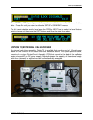
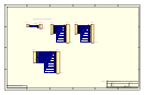
The PCA is constructed such that it plugs through the rear panel into the Control Output
connector, J1008, on the calibrator’s motherboard (please see the manual for your calibrator
for details). When one of the Control Outputs is energized, it causes the base of the
associated PNP valve driver transistor, U1 through U8 to be taken to ground and thereby into
the emitter-collector junction into full conduction. Please note that this interface sources
DC
current to the valves rather than previous versions that sinks
current from an external supply
through the valve in question.
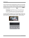
Valves should be connected between one of the Valve Drive outputs and one
of the Return pins.
The external power supply must be connected to the Valve Driver Interface
using the +12V coaxial input connector on the rear top right of the assembly.
The external supply in turn must be connected to 85-264V, 47-63Hz mains.
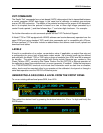
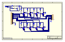
The Valve Driver Outputs are mapped one-for-one to the Control Outputs 1 through 8 and can
be manually actuated for troubleshooting using the Signal-I/O diagnostic function in the
calibrator’s software. However, the drive outputs are mapped In reverse to the status control
bits such that Bit-0 (LSB) is valve drive 8 and Bit-7 is valve drive 1. (Schematics attached).