


11
It is recommended that only an authorized Countryside installer install your pellet/corn stove. The following installation
guidelines must be followed to ensure conformity with both the safety listing of this stove and to local building codes.
9 A listed 3” or 4” type “PL” pellet vent exhaust system must be used for FREESTANDING installation and attached to the
pipe connector provided on the back of the stove. Use a 3” to 4” adapter for 4” pipe. A cap must be used at the
termination of type “L” vent chimneys.
9 Do not terminate vent in any enclosed or semi-enclosed area, such as; carports, garage, attic, crawl space, under a sundeck
or porch, narrow walkway or closed area, or any location that can build up a concentration of fumes such as a stairwell,
covered breezeway, etc.
9 Vent surfaces can get hot enough to cause burns if touched by children. Non-combustible shielding or guards may be
required. Do not install a flue damper in the exhaust vent of this unit.
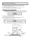
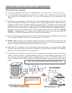
9 Termination must exhaust above air inlet elevation. It is recommended
that at least 5 ft. of vertical pipe be installed
when the appliance is vented directly through a wall or in a basement. This will create some natural draft to prevent
the possibility of smoke or odor during appliance shutdown and to keep exhaust from causing a nuisance or hazard from
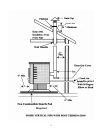
exposing people or shrubs to high temperatures. In any case, the safest and preferred venting method is to extend the vent
through the roof. Do not connect this unit to a chimney flue serving another appliance.
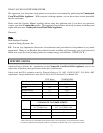
9 Distance from doors and windows, gravity or ventilation air inlet into building:
Not less that 4 ft. / 1.2 m below, 4 ft. / 1.2 m horizontally from, 1 ft. / 305 mm above (This does not apply if the
Windows are non-opening or have been fixed so they cannot open.)
9 Distance from bottom of termination and grade – 1 ft. / 305 mm minimum. This is conditional upon the plants and nature
of grade surface. The exhaust gases are not hot enough to ignite grass, plants or shrubs located in the vicinity of the
termination. The grade surface must not be a lawn. Distance from bottom of termination and public walkway is 7ft. /2.1m
minimum.
9 Distance to combustible materials – 2 ft. / 610 mm. This includes adjacent building, fences, protruding parts of the
structure, roof overhang plants and shrubs, etc.
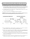
9 It is recommended that a single or double clean-out “tee”, for cleaning the vent in both directions, be installed at every 90
0
junction
to enable collection of fly ash and to permit periodic cleaning of the exhaust system. 90
0
elbows accumulate fly-
ash and soot thereby reducing exhaust flow and performance of the stove.
9 Total length of horizontal vent must not exceed 48” (4 ft.) / 1,200 mm. All joints in the vent system must be fastened by at
least 3 screws, and all joints must be sealed with RTV silicone sealer to be airtight.
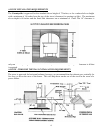
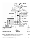
9 A 3” single-wall, stainless steel flexible or rigid exhaust pipe should be used for INSERT installations and must be
attached to the stove with a single-wall, stainless steel “tee” with a clean-out cap. The stainless steel “tee” should be
inclined at 45
0
to enable the vent to be centered on the stove and allow the “tee” to be cleaned without removing the stove
(see diagram on page 17).
9 When venting into an existing masonry or factory built chimney, the chimney must be cleaned, with all creosote removed.
The chimney must be a type suited for solid fuel. WARNING: The chimney and the chimney connections must be kept
clean and in good condition.
9 The “PL” vent or single wall stainless exhaust system must be installed so as to be GAS TIGHT! The vent manufacturer’s
installation procedures must be followed. In addition, pipe connections, joints and all pipe seams within the home should
be sealed with high temperature RTV silicone sealer.
9 If an insert is to be installed into an unlined masonry chimney, it is recommended that at 3” or 4” stainless steel pipe be
extended to the top of the existing chimney. The top of the existing chimney should be sealed with a steel plate (see
diagram on page 17).
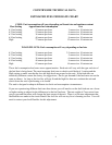
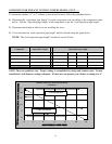
GUIDELINES FOR EXHAUST VENTING SYSTEMS DESIGN