APPLICATIONS GUIDE: SYSTEM SMOKE DETECTORS
6
Class A Circuits
Class A circuits also differentiate between short circuits
across the loop and opens on the loop. Supervision is
accomplished by monitoring the level of current passing
through the installation wiring and the end-of-line resistor,
which in a Class A circuit is an integral part of the fire
alarm control panel. Class A wiring must return to and be
terminated in the control panel. This technique requires a
minimum of four conductors to be terminated at the panel,
and further requires that the fire alarm control panel is
designed to monitor Class A circuits. The additional cir-
cuitry necessary for Class A supervision enables the con-
trol panel to “condition” the initiating circuit to monitor
the initiating circuit from both ends when in a trouble
mode due to an open fault on the loop. This “conditioning”
ensures that all devices are capable of responding and
reporting an alarm despite a single open or non-simultane-
ous single ground fault on a circuit conductor.
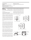
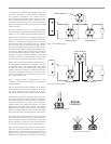
The compatibility considerations of smoke detectors that
were detailed in Class B circuits apply with Class A as well
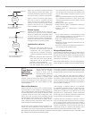
(Figure 11).
INITIATING DEVICE
CIRCUIT
ZONE 1
INITIATING DEVICE
CIRCUIT RETURN
TROUBLE ALARM
FIRE ALARM CONTROL UNIT
PRIMARY
POWER
SUPPLY
TYPICAL
INITIATING
DEVICES
Figure 11: 2-Wire Detectors – Style D (Class A) Circuit
Wireless Circuits
Wireless detectors and their internal transmitters derive
their operating power from their internal battery or batter-
ies and are listed by Underwriters Laboratories, Inc. in
accordance with requirements of NFPA 72. Supervision of
the internal battery power source is incorporated within
the smoke detector circuitry. If the battery power source
depletes to the threshold specified by Underwriters
Laboratories, the smoke detector will sound a local alert
and initiate a trouble signal once each hour for a minimum
of seven days or until the battery or batteries are replaced.
The wireless initiating devices are supervised for tamper
and/or removal by initiating a distinct trouble signal. Each
wireless device also initiates a test transmission every hour
to verify the reliability of the communication circuit. Any
device failing to communicate is identified on the control
panel no less than every four hours.
General Zoning Guidelines
The faster the source of an alarm can be pinpointed, the
faster action can be taken. Although formal rules for zon-
ing are not given in fire protection codes, except for wire-
less devices where each smoke detector must be individu-
ally identified, it is always sensible to zone any system that
contains more than a small number of detectors.
Experienced detector installers and system designers rec-
ommend the following:
• Establish at least one zone on every protected floor.
• Zone natural subdivisions of a large building, such as
separate wings on a single floor.
• Minimize the number of detectors in each zone. Fewer
detectors on a zone will speed up locating the fire and
simplify troubleshooting.
• Install duct detectors in different zones than open-area
detectors for troubleshooting and locating purposes.
Fire Safety Functions
Often smoke detectors are utilized to control ancillary
equipment. Most detectors used in releasing service have
auxiliary relay contacts which are directly connected to the
system or device to be controlled. Care should be taken to
ensure that detectors utilized in such a manner are
approved for releasing service. A few of the typical appli-
cations are as follows:
•To control the flow of smoke in air handling and air
conditioning systems.
•To release doors to contain smoke in a fire situation.
•To release locks to allow exit in a fire situation.
•To capture and recall elevators in a fire situation.
•To activate a suppression system.
Spacing and placement requirements for detectors used in
releasing service may be different from detectors used in
conventional open area applications. It is recommended
that 4-wire detectors be used in these situations because
depending on the control panel and detectors used, more
than one detector relay on a circuit may not receive enough
power from the 2-wire circuit to operate during alarm.
Smoke Detector Installation
Wiring Installation Guidelines
All fire alarm system installation wiring should be installed
in compliance with Article 760 of NFPA 70, the National
Electrical Code (NEC), the manufacturer’s instructions and
the requirements of the authority having jurisdiction.
Typical Wiring Techniques
The primary rule of installation wiring is:
“Follow the Manufacturer’s Instructions”
This rule cannot be overemphasized. The requirement for
electrical supervision of the installation wires and their
connections to initiating devices makes fire alarm system
installation wiring very different than general wiring.


