


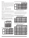
NOTE: SpectrAlert selectable output strobes, set at 15 and 15/75cd,
automatically work on both 12V and 24V power supplies.
NOTE: The strobe is not listed for 12V operating voltages when
set to 30, 75 or 110 candelas. Use only those settings marked as
OK in the chart above.
NOTE: The low volume setting of some tones must NOT be used
for public mode applications when the device is powered from a 12-
volt panel. Refer to the Sound Output Guide on the previous page.
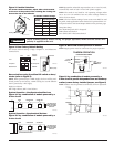
Temp/Non-Temp
ON=NON-Temporal, OFF=Temporal
3KHz/Electromechanical
ON=3KHz, OFF=Electromechanical
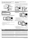
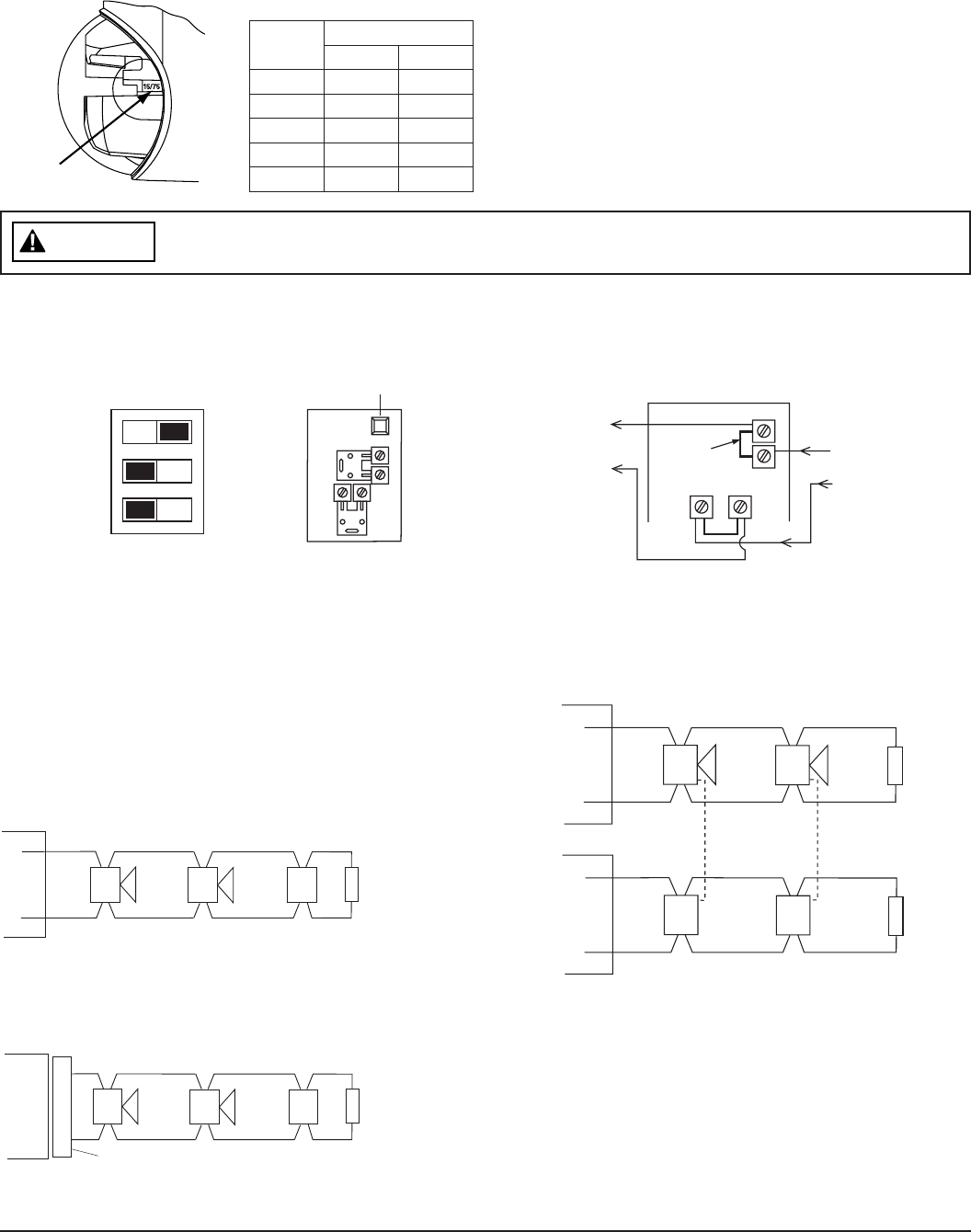
Figure 5: Horns and strobes powered in tandem
NOTE: Supply power must be continuous for proper operation.
FROM:
FACP, MODULE
OR PREVIOUS
DEVICE
TO NEXT
DEVICE OR
EOL
+
–
Strobe +
Strobe – Horn –
Horn +
TANDEM OPERATION
HORN/STROBE COMBO
FACTORY
INSTALLED
JUMPERS
Figure 6: Any combination of models powered by a
4-wire circuit to provide independent horn and strobe op-
eration (remove factory installed jumpers, see Figure 8)
NOTE: Strobes must be powered continuously for horn operation.
(+)
(–)
(+)
(–)
(+)
(–)
FOUR WIRE SYSTEM
COMBO MODELS
WIRED FOR INDEPENDENT
OPERATION
(HORN CAN BE TURNED OFF
AT THE PANEL WHILE STROBES
CONTINUE TO OPERATE)
E
O
L
(+)
(–)
(+)
(–)
(+)
(–)
E
O
L
S
T
R
O
B
E
C
O
M
B
O
H
O
R
N
H
O
R
N
S
T
R
O
B
E
D900-28-00 3 I56-1796-011R
A0111-00
A0113-00
Figure 2: Candela Selections
For strobe candela selection, adjust slide switch located
on the rear of the product while watching the viewing win-
dow on the side of the reflector.
Viewing Window
A0133-00
Permissible Candela Settings:
Candela
Setting
Operating Voltage
12V 24V
15 OK OK
15/75 OK OK
30 OK
75 OK
110 OK
Check terminal polarity before wiring. For proper operation, make sure the correct wire
polarity is applied to the unit.
WARNING
Figure 3: Horn Factory Default Setting
The factory default setting is High, Temporal 3, and Electrome-
chanical tone.
Low
OFF ON
Temporal
Electromech.
DIP Switch
Factory
Default
High
Non-Temporal
3000Hz
Base (rear)
Horn selections using 3-position DIP switch on horn/
strobe (refer to Figure 3):
NOTE: When powered from a FWR supply, the horn will be mod-
ulated (turned on and off) by 120Hz causing it to sound different
than if powered by a DC supply.
High/Low Volume
ON=High Volume, OFF=Low Volume
System Operation – Non-Synchronized Devices:
Figure 4a: Any combination of models powered by a
2-wire circuit:
HORN
(+)
(–)
(+)
(–)
E
O
L
(+)
(–)
(+)
(–)
HORN/STROBE
STROBE ONLY
TWO WIRE SYSTEM
ANY MIX OF MODELS
WIRED FOR TANDEM
OPERATION
HORN
SYNCHRONIZATION MODULE
MDL
(+)
(–)
(+)
(–)
E
O
L
(+)
(–)
(+)
(–)
HORN/STROBE
STROBE ONLY
TWO WIRE SYSTEM
ANY MIX OF MODELS
WIRED FOR TANDEM
OPERATION
System Operation – Synchronized Devices:
Figure 4b: Any combination of models powered by a
2-wire circuit:
HORN
(+)
(–)
(+)
(–)
E
O
L
(+)
(–)
(+)
(–)
HORN/STROBE
STROBE ONLY
TWO WIRE SYSTEM
ANY MIX OF MODELS
WIRED FOR TANDEM
OPERATION
HORN
SYNCHRONIZATION MODULE
MDL
(+)
(–)
(+)
(–)
E
O
L
(+)
(–)
(+)
(–)
HORN/STROBE
STROBE ONLY
TWO WIRE SYSTEM
ANY MIX OF MODELS
WIRED FOR TANDEM
OPERATION
A0111-00
A0110-00
A0112-00