


D900-28-00 2 I56-1796-011R
Wire Sizes
The designer must be sure that the last device on the circuit has
sufficient voltage to operate the device within its rated voltage.
When calculating the voltage available to the last device, it is nec
-
essary to consider the voltage drop due to the resistance of the
wire. The thicker the wire, the less the voltage drop. Generally, for
purposes of determining the wire size necessary for the system, it
is best to consider all of the devices as “lumped” on the end of the
supply circuit (simulates “worst case”).
Typical wire size resistance:
18 AWG solid: Approximately 8 ohms/1,000 ft.
16 AWG solid: Approximately 5 ohms/1,000 ft.
14 AWG solid: Approximately 3 ohms/1,000 ft.
12 AWG solid: Approximately 2 ohms/1,000 ft.
Example: Assume you have 10 devices on a zone and each re
-
quires 50 mA average and 2000 Ft. of 14 AWG wiring (total
length=outgoing +return). The voltage at the end of the loop is
0.050 amps per device x 10 devices x 3 ohms/1,000 ft. x 2000 ft
=3 volts drop.
NOTE: If class “A” wiring is installed, the wire length may be up
to 4 times the single wire length in this calculation.
The same number of devices using 12 AWG wire will produce only
2 volts drop. The same devices using 18 AWG wire will produce
8 volts drop. Consult your panel manufacturer’s specifications, as
well as SpectrAlert’s operating voltage range to determine accept
-
able voltage drop.
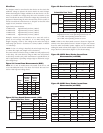
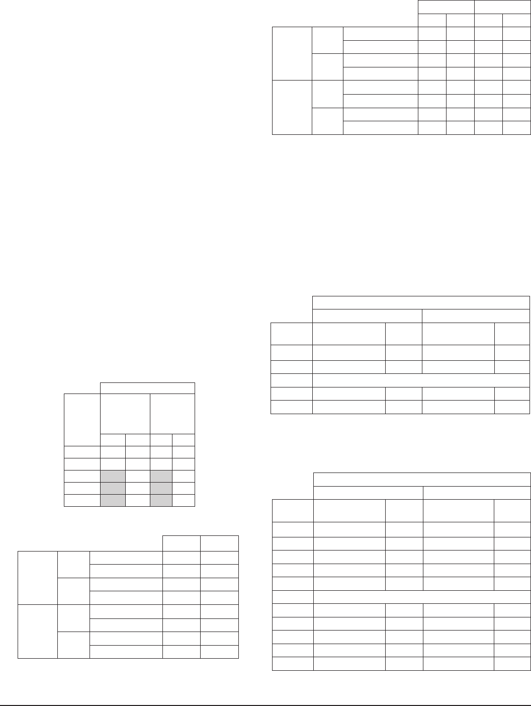
Figure 1A: Current Draw Measurements (RMS)
NOTE: All ‘S’ and ‘P’ models were only tested at the 8-17.5 and
16-33 Volt-FWR/DC limits. This does not include the 80% low-
end or 110% high-end voltage limits.
Strobe Current Draw
Candela
Setting
FWR
Operating
Current
Strobe
DC
Operating
Current
Strobe
12V 24V 12V 24V
15
112 64 127 59
15/75
135 74 127 69
30
93 90
75
158 160
110
208 209
Figure 1B: Horn Sound Measurements (dBA):
Selectable Horn Tones
8-17.5V 16-33V
Temporal Low
Volume
Electromechanical 67 75
3000 Hz Interrupted 68 75
High
Volume
Electromechanical 71 80
3000 Hz Interrupted 72 81
Non-
Temporal
Low
Volume
Electromechanical
71 79
3000 Hz Interrupted 72 79
High
Volume
Electromechanical 76 84
3000 Hz Interrupted 77 86
Figure 1C: Horn Current Draw Measurements (RMS):
Selectable Horn Tones
DC FWR
12V 24V 12V 24V
Temporal Low
Volume
Electromechanical 15 23 13 23
3000 Hz Interrupted 15 33 13 23
High
Volume
Electromechanical 36 53 20 44
3000 Hz Interrupted 43 57 21 40
Non-
Temporal
Low
Volume
Electromechanical
16 37 19 29
3000 Hz Interrupted 16 32 18 33
High
Volume
Electromechanical 38 49 46 49
3000 Hz Interrupted 44 56 42 58
NOTE: Regulated 12 VDC, max operating current 44.4 mA
Regulated 24 VDC, max operating current 57.0 mA
12 V FWR, max operating current 45.7 mA
24 V FWR, max operating current 57.5 mA
NOTE: 12VDC 2-wire horn/strobe current is shown in Figure 1D.
24VDC 2-wire horn/strobe current is shown in Figure 1E. Current
draw for other horn/strobe power supplies can be calculated by
adding the strobe current draw (Figure 1A) for chosen candela set
-
ting to the horn current draw (Figure 1C) for chosen setting.
Figure 1D: 12VDC Horn/Strobe Current Draw
Measurements (mA RMS)
Temporal
Low Volume High Volume
Candela
Setting
Electromechanical 3000 Hz Electromechanical 3000 Hz
15 111 111 112 112
15/75 127 127 126 129
Non-Temporal
15 113 112 114 115
15/75 128 128 130 134
Figure 1E: 24VDC Horn/Strobe Current Draw
Measurements (mA RMS)
Temporal
Low Volume High Volume
Candela
Setting
Electromechanical 3000 Hz Electromechanical 3000 Hz
15 71 70 73 75
15/75 86 85 87 88
30 99 98 100 100
75 166 166 167 170
110 209 209 210 213
Non-Temporal
15 74 74 79 82
15/75 86 88 93 96
30 101 101 107 110
75 167 167 173 176
110 213 213 218 222