


NOTE: DIAGRAMS & ILLUSTRATION NOT TO SCALE.
9
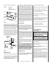
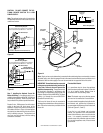
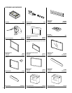
Finished Wall Details
It is sometimes best to frame the appliance
after it has been positioned in place. Frame with
2 x 4s or heavier lumber. Always frame in
accordance with local building codes.
Note: The header may rest on the top spacers
but must not be notched to fit around them.
In order to install the appliance facing flush with
the finished wall, position the framework to
accommodate the thickness of the finished wall
(
Refer to Figures 2, 3 and 5
).
If you live in a cold climate, seal all cracks
around your appliance with noncombustible
material and wherever cold air could enter the
room. It is especially important to insulate
outside chase cavity between studs and under
floor on which appliance rests, if floor is above
ground level.
CAUTION: DO NOT CONNECT THE OP-
TIONAL REMOTE SWITCH TO A 120V
POWER SUPPLY.
Note: The optional rocker switch is mounted to
the appliance and wired in the same way as the
remote wall switch.
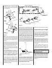
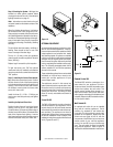
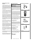
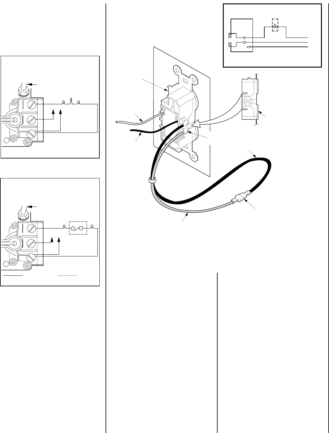
Step 7. Installing the Optional Forced Air
Blower Kit Wiring – A receptacle plate is pro-
vided for the installation of the FAB-1100 forced
air blower kit (optional). Electrical power must
be provided to this plate to operate the blower.
Route a 3-wire, 120Vac power line with control
switch to the lower left front corner of the
appliance. Supply wires are to be connected to
the outlet as shown in
Figure 14
, ensuring that
the polarity (as determined by the colors of the
wires) is exactly as shown. The black and red
wire loop must be left intact, with the mating
connectors connected.
IMPORTANT: Ground lead must be connected
to the green screw located on the junction box
cover plate. Failure to do so will prevent the
appliance from operating. The appliance must
be electrically grounded in accordance with
local codes or, in the absence of local codes, the
National Electrical Code, ANSI/NFPA 70-(latest
edition). (In Canada, the current CSA C22-1
Canadian Electrical Code.)
The forced air blower kit may be mounted at
initial appliance installation or at any time there-
after. Follow the instructions provided with the
blower kit.
Figure 14
White
(Supply)
Black
(Supply)
Bipolar
Terminal
Screw
Blower
(Lower)
Outlet
Black
Wire
Mating
Connectors
Red Wire
120 Vac
60 Hz
Blower Wiring Diagram
}
OFF/ON Blower
Wall Switch
To Fuse or
Circuit Breaker
120V
AC
60Hz
Fireplace
Junction Box
Black
White
Receptacle
Ground Wire
Connection
Note: Supply wires may be alternatively connected to the outlet using the screw terminals, however
the black supply wire must be ganged wired to the same terminal that the pre-wired black wire is
attached to and the white supply wire must be connected to the opposite side of the outlet.
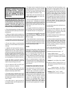
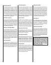
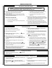
VFST Series
Standard Wiring Diagram
TPTH TP TH
Thermopile
If any of the original wire as supplied must be replaced, it
must be replaced with Type AWM 105°C – 18 GA. wire.
* For Rocker or ON/OFF Wall Switch Attachment Only.
**
From Thermocouple
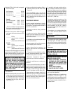
VFST Series
Optional Wiring Diagram
TPTH TP TH
Thermopile
If any of the original wire as supplied must be replaced, it
must be replaced with Type AWM 105°C – 18 GA. wire.
Optional ON/OFF
Wall Switch/Rocker Switch
Factory Wired Field Wired
*
* For Rocker Switch Attachment Only.
*
From Thermocouple
Figure 13
Figure 12