


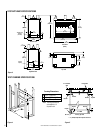
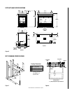
NOTE: DIAGRAMS & ILLUSTRATION NOT TO SCALE.
11
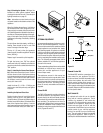
Figure 19
OPTIONAL EQUIPMENT
An incomparable package of options are avail-
able for use with these appliances. These op-
tions can both customize the operation of these
unique appliances and enhance their beauty
and charming appeal. All options are available
in kit form, are easy to install and are packaged
complete with all required parts and instruc-
tions. Some of the option kits need to be fitted
prior to completing the installation of the appli-
ance. The following paragraphs detail the kit
options available for use with the appliances
covered in this manual.
These outstanding optional items can be added
individually or in sets of two or more to cus-
tomize your vent-free appliance to fit your
homes unique needs.
The appliances covered in this manual are
heater rated and produce a great deal of heat.
Decorative brass trim pieces and hoods may
tarnish because of their proximity to the heater
opening and front face. Tarnishing of these
pieces is normal, unavoidable and should be
expected.
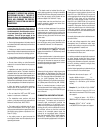
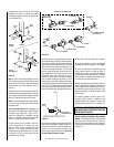
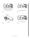
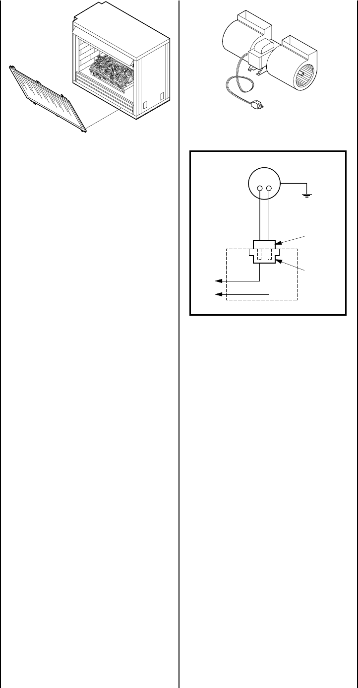
Forced Air Kit
The FAB-1100 assembly provides a forced air
circulation feature for your appliance. This kit
mounts directly into the lower intake chamber
with an electrical connection made at the recep-
tacle provided. The appliance must have an
independent 120Vac power line incorporated at
the time of installation. Refer to Step 6 of the
installation instructions supplied with the forced
air kit (
Figures 20 and 21
).
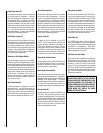
Figure 20
Grounded
to Appliance
Blower Motor
Motor Plug
Receptacle
120V
Appliance Junction Box
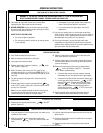
Step 9. Checking the System – With gas line
installed run initial system checkout before
closing up the front of the unit. Follow the pilot
lighting instructions on page 15.
Note: Instructions are also found on the pull
out panel located on the bottom surface of the
appliance.
When first lighting the appliance, it will take a
few minutes for the line to purge itself of air.
Once purging is complete, the pilot and burner
will light and operate as indicated in the instruc-
tion manual. Subsequent lightings of the appli-
ance will not require such purging. Inspect the
pilot flame (remove logs, if necessary, handling
carefully).
The pilot flame should be steady, not lifting or
floating. Flame should be blue in color with
traces of orange at the outer edge.
The top ³⁄₈" (10 mm) at the pilot generator
(thermocouple) should be engulfed in the pilot
flame (NG only).
Replace logs if removed for pilot inspection.
To light the burner; turn “ON” the optional
remote wall switch (if installed) and rotate the
gas valve control knob counterclockwise to the
“ON” position.
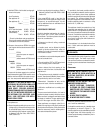
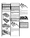
Step 10. Installing the Screen Panel Assem-
bly – Retrieve the screen door frame. Position
the door frame in front of the firebox opening
in the brackets at the base of the fireplace front
opening. Lean the door frame back towards
the fireplace ensuring that the frame seats
evenly as it draws shut.
Install the three (3) ¹⁄₄"-20 x 1" Phillips pan
head screws removed previously and tighten
to secure.
Installing the Optional Glass Door
Position the door frame in front of the firebox
opening, with the joint in the gasket down.
Locate the three (3) tabs at the bottom edge of
the door frame into the three (3) brackets at the
base of the fireplace front opening. Lean the
door frame back towards the fireplace ensuring
that the frame seats evenly as it draws shut.
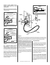
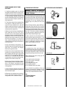
Figure 21
Remote Control Kit
The Model RCK adds the convenience of re-
mote control for your appliance. The kit in-
cludes a wireless, hand held transmitter and a
receiver that replaces the wall switch. This
special receiver permits either manual or re-
mote control modes. Both receiver and trans-
mitter operate on standard 9 volt batteries (not
included). Refer to the RCK installation instruc-
tion for specific details.
Wall Switch Kit
An optional wall switch kit can be installed
along with all vent-free appliances. The kit
consists of a standard UL wall switch with
cover plate. This kit provides for remote (wall)
operation of the appliance. Replace the wall
switch and cover plate of this kit with the
components of the RCK and you can have true
remote control of your vent-free appliance,
turning it on and off from your favorite easy
chair. The wall switch kit should be installed
along with the appliance. Refer to
Figure 13
and Step 6 for detailed installation instructions.