


36
NOTE: DIAGRAMS & ILLUSTRATIONS ARE NOT TO SCALE.
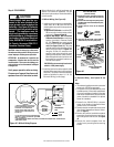
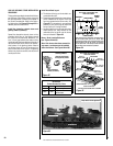
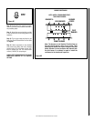
SIT Millivolt Gas Valve
Pilot for SIT Millivolt
Gas Valve
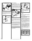
Figure 62
Step 6. See Figure 62 and remove the pilot
hood assembly to access the hexed pilot orifice.
Remove and replace the orifice with the one
provided with the kit.
Pressure
Regulator
Remove
These
Components
Figure 61
Pilot
Orifice
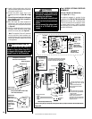
P
S
I
OFF
I
ON
CONTROL
I
G
N
I
T
E
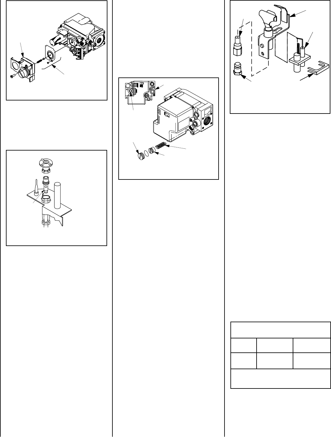
Gas Valve
Assembly
Manifold
Pressure
Test Port
Slotted
Cap
Spring
Adjusting
Screw
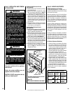
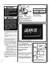
Figure 64
Figure 63
All Models
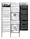
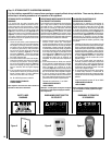
Step 9. (Refer to Figure 60 on Page 35 and
Figure 65 on Page 37)
VERIFY THE PROPER ORIFICE SIZES
BEFORE INSTALLING THEM.
A. Remove the two orifices from the manifold
and replace them with the ones provided in the
kit. Table 10 shows the orifice sizes for natural
and propane models. Figure 65 illustrates the
orifice. Use pipe joint compound or Teflon
tape on all pipe fittings before installing (en-
sure propane resistant compounds are used
in propane applications, do not use pipe joint
compounds on flare fittings).
B. Install rear burner first, followed by front
burner, as shown in Figure 66 on Page 37.
Ensure that the arm of the venturi of each burner
is hooked onto the air shutter adjustment lever
(refer to Figure 60 on Page 35). The primary air
opening can be adjusted by rotating the adjust-
ment lever from beneath the firebox floor. Refer
to Figure 57 on Page 31 for the recommended
minimum primary air opening setting.
NOTE: Each model has two burners and 2
Orifices.
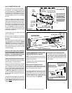
Pilot
Orifice
Pilot
Assembly
Igniter
Assembly
Retaining
Clip
Flare Nut
Note: If the igniter is damaged, a replacement kit
is available, order Catalog No. 87L54.
Electronic Appliances
Step 7. Honeywell Electronic Valves - See
Figure 63 and the instructions provided with
the kit. Remove the slotted cap screw, o-ring,
pressure-regulating adjusting screw and spring.
Retain all parts for possible later use. Install
new components from the kit. Black cap and
red spring for propane gas appliances. Silver
cap and stainless steel spring for natural gas
appliances.
Step 8. See Figure 64 and replace the pilot
orifice as follows: Remove the igniter assembly
retainer clip, and carefully remove the igniter
assembly.
Remove the screw securing the pilot assembly
to its mounting bracket. Back off the flare nut
at the end of the pilot gas line to free the pilot
assembly from the gas line. Remove the pilot
orifice and replace it with the one provided with
the conversion kit. Reinstall the pilot assembly
by reversing the steps detailed here.
When reinstalling the igniter assembly, use
extreme care to prevent damage and break-
age. Do not apply any leverage to the igniter
assembly while restoring the retainer clip to
its original position.
Burner Orifice Sizes
Elevation 0-4500 feet ( 0-1372 meters)
Model
Series
Nat.Gas
drill size (inches)
Propane
drill size (inches)
SSDVST
SSDVPF
#44 (.086")
*
60J80 •
#55 (.052")
**
19L52 •
Table 10
* Standard size installed at factory
** Standard size in LP conversion kit
• Part /Cat. Number