


NOTE: DIAGRAMS & ILLUSTRATIONS ARE NOT TO SCALE.
13
Securing Screws
(OUTSIDE OF
APPLI
ANCE)
Insulation
Top Vent
Vent Seal Cap
Firebox Top
Cabinet Top
CROSS SECTION
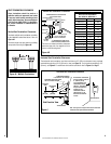
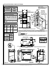
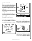
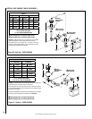
SIDE VENT SEAL CAP REMOVAL
(SIDE VENT INSTALLATIONS ONLY)
Insulation
Vent Seal Cap
Securing Screws
Side Vent
Cabinet Back
CROSS SECTION
(INSIDE of Appli
ance)
(OUTSIDE of
Appli
ance)
(INSIDE of
Appli
ance)
WARNING
The VENT SEAL CAP must remain securely installed
on unused vent collar. Failure to do so could result in
leakage of flue products into living space.
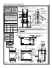
Figure 17
Figure 15 -
Figure 16 -
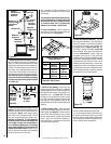
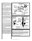
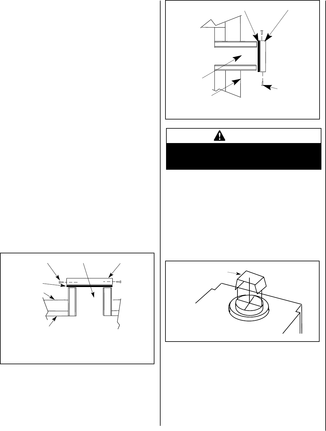
Installation of Vent Restrictor
(Top Vent Installations with Vertical Terminations Only)
A vent restrictor (provided) may be needed with this appliance. If needed,
install the vent restrictor in the appliance top flue outlet as shown in
Figure 17 when vertically terminating the vent system above the roof. It
may be installed either from inside or outside the appliance, in the inner
fireplace collar. It is press-fitted in place.
Note: The restrictor is included within the firebox.
Restrictor
Appliance Top
Vent Outlet
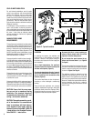
TOP VENT SEAL CAP REMOVAL
(TOP VENT INSTALLATIONS ONLY)
Vent Restrictor
Installation
(Top Vent)
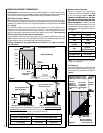
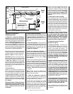
Step 3. INSTALL THE VENT SYSTEM
General Information
These instructions should be used as a guideline and do not supersede
local codes in any way. Install venting according to local codes, these
instructions, the current National Fuel Gas Code (ANSI-Z223.1) in the
USA or the current standards of CAN/CSA-B149.1 in Canada.
Ensure clearances are in accordance with local installation codes and
the requirements of the gas supplier.
Dégagement conforme aux codes d'installation locaux et aux exigences
du foumisseunde gaz.
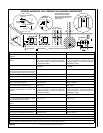
Use only approved venting components. See Approved Vent
Components on Page 2.
These fireplaces must be vented directly to the outside.
The vent system may not service multiple appliances, and must never
be connected to a flue serving a solid fuel burning appliance. The vent
pipe is tested to be run inside an enclosed wall (such as a chase). There
is no requirement for inspection openings in the enclosing wall at any of
the joints in the vent pipe.
REMOVE VENT SEAL CAP
(From the vent that will be used only)
Top Vent - See Figure 15 and Side Vent - See Figure 16
Preparing the Appliance Vent Collar
Each of the appliances' two vent collars are sealed with a seal cap which
must be removed from the vent collar being used. Refer to Figure 15
for top vent installations and Figure 16 for side vent installations and
the following steps to prepare the appropriate collar for use.
From the vent collar being used, remove the two screws securing the
vent seal cap. Twist the cap counterclockwise. Pull it away from the
appliance and discard, along with the piece of insulation.
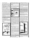
Select Venting System - Horizontal or Vertical
With the appliance secured in framing, determine vent routing and identify
the exterior termination location. The following sections describe vertical
(roof) and horizontal (exterior wall) vent applications. Refer to the section
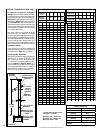
relating to your installation. A list of approved venting components is
shown on Pages 33 and 34.