


30
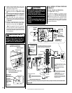
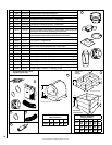
NOTE: DIAGRAMS & ILLUSTRATIONS ARE NOT TO SCALE.
30
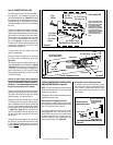
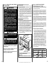
Step 10. BURNER ADJUSTMENTS
Flame Appearance and sooting
Proper flame appearance is a flame which is
blue at the base and becomes yellowish-orange
in the body of the flame.
When the appliance is first lit, the entire flame
may be blue and will gradually turn yellowish-
orange during the first 15 minutes of operation.
After 15 minutes of operation, if the flame is
blue, or if the flame is orange with evidence of
sooting (black tip), the air shutter opening may
need to be adjusted.
If the air shutter openings are closed too far,
sooting may develop. Sooting is indicated by
black puffs developing at the tips of very long
orange flames. Sooting results in black deposits
forming on the logs, appliance inside surfaces
and on exterior surfaces adjacent to the vent
termination.
Sooting is caused by incomplete combustion
in the flames and lack of combustion air enter-
ing the air shutter opening. To achieve a warm
yellowish-orange flame with an orange body
that does not soot, the shutter opening must be
adjusted between these two extremes.
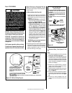
Air Shutter Adjustment Guidelines
• If there is smoke or soot present, rst check
the log set positioning to ensure that the
flames are not impinging on any of the logs.
If the log set is properly positioned and a
sooting condition still exists, then the air
shutter opening should be increased.
• The more offsets in the vent system, the larger
the air shutter opening will need to be.
• An appliance operated with the air shutter
opened too far, may have flames that appear
blue and transparent. These weak, blue and
transparent flames are termed anemic.
• Propane models may exhibit ames which
candle or appear stringy. If this is present and
persists, adjust the air shutter to a more closed
position, then operate the appliance for a few
more minutes to ensure that the flame normal-
izes and the flames do not appear sooty.
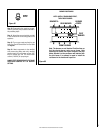
The following chart is provided to aid you in
achieving the correct air shutter adjustment
for your installation.
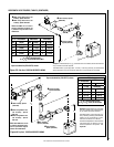
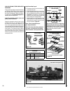
Top Flange on
Glass Door
Bottom Vee-flange
Glass Door
Glass Door Latch
Glass Door
Firebox Floor
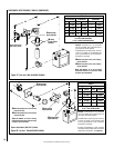
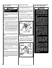
Air Shutter Adjustment Guidelines:
Amount of
Primary Air
Flame
Color
Air Shutter
Adjustment
If air shutter is
closed too far
Flame will
be orange
Air shutter
gap should be
increased
If air shutter is
open too far
Flame will
be blue
Air shutter
gap should be
decreased
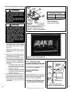
Step 9. INSTALLATION AND REMOVAL
OF GLASS DOOR
Only doors certified with the appliance
shall be used.
Seules des portes certifiées pour cet
appareil doivent être utilisées.
CAUTION: DO NOT abuse glass door by
striking or slamming shut.
WARNING
• Do not attempt to substitute the
materials used on these doors,
or replace cracked or broken
glass.
• Handle this glass with extreme
care! Glass is susceptible to
damage – Do not scratch or
handle roughly while reinstall-
ing the glass door frame.
• The glass door(s) of this appli-
ance must only be replaced as
a complete unit as provided
by the manufacturer. Do not
attempt to replace broken,
cracked or chipped glass sepa-
rately.
• Do not attempt to touch the
front enclosure glass with your
hands while the fireplace is in
use.
WARNING
Do not operate appliance with
the glass front removed, cracked
or broken.
AVERTISSEMENT
Ne pas utiliser l'appareil si le
panneau frontal en verre n'est
pas en place, est craqué ou
brisé.
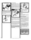
Removing Glass Enclosure Panels
(see Figure 56)
1. Remove the top louver assembly by lifting it
up and pulling it out.
2. Remove the control compartment access
door (see removal instructions on Page 27
- Removing Control Compartment Door).
3. Locate the two (2) latches at the top of the
control compartment. To disengage the two
latches from the bottom vee-flange of the
glass enclosure panel, reach for the handles
located towards the back of the latches and
pull the handles down toward the front of
the appliance.
4. Swing the bottom of the door out and raise
it slightly to lift the top flange of the door
frame away from the appliance.
Installing Glass Enclosure Panels
(see Figure 56)
1. Visually inspect the gasket on the backside of the
glass panel. The gasket surface must be clean,
free of irregularities and seated firmly.
2. Position the glass enclosure panel in front of
the firebox opening at a 45 degree angle and
engage the top flange over the lip at the top
of the firebox opening. See Figure 56.
3. Swing the glass enclosure panel down and
back. Ensure the gasket seats evenly as the
panel draws shut. Engage the Vee-flange at
the bottom of the panel with the latches and
close the latches to secure the panel.
4. Reinstall top louver assembly and control
compartment door see installation instruc-
tions on Page 27, Reinstalling Control
Compartment Door).
INSTALLING OR REMOVING GLASS DOOR
Figure 56 -
Note: When installing the glass door, ensure the
spacing on both sides are equal.