


26
NOTE: DIAGRAMS & ILLUSTRATIONS ARE NOT TO SCALE.
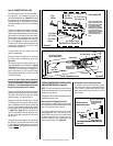
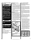
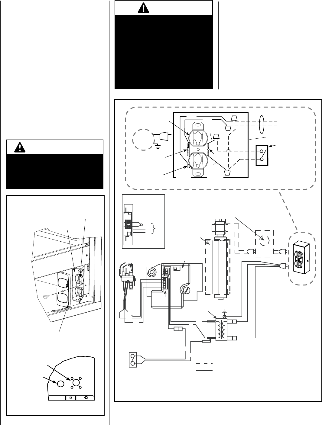
Step 5. WIRING - OPTIONAL FORCED AIR
BLOWER KIT
FBK-100, FBK-200 and FBK-250 Kits
(See Figure 46 for wiring) -
An electrical receptacle is provided for the
installation of the FBK-100, FBK-200 and FBK-
250 forced air blower kits. Electrical power
must be connected to this receptacle in order
to operate these blowers. Install the blower
kits according to the installation instructions
provided with the kits.
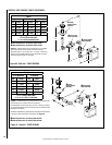
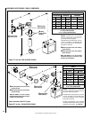
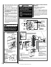
Figure 45
Outlet Receptacle
Junction Box
Field-provided Metal Junction Box
Cover Plate With Screw
View Of Right
Bottom Corner Of Unit
Receptacle, Junction Box
and Cover Plate Installation
Fireplace
Side
Junction Box
knock-out (2
places each side)
Valve Access Side
Press snap
bushing into the
knock-out for
control switch
wires.
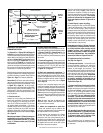
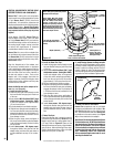
CAUTIONS
•
Remove the carton support from
the control compartment before
operating the appliance.
•
Ensure that wires are positioned
away from hot surfaces and sharp
edges.
•
Do not connect the optional wall
switch to a 120 Volt AC power
supply.
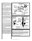
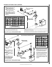
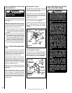
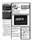
Electronic Wiring Diagram (Honeywell) Showing Blower Wiring for Optional FBK-100, FBK-200 & FBK-250 Kits
Schematic Representation Only
Relay Module C/W FBK-250 only. Plug blower
into J-Box receptacle for FBK-100 or FBK-200
application. See View A for J-Box wiring.
Optional Blower
*OFF/ON Switch
(Integral with
Gas Valve)
Honeywell
Electronic
Gas
Valve
120 VAC
Primary
Secondary
Optional Control Switch
Junction Box
Pilot Burner
Assembly
BL
BL
Field Wired
Factory
Wired
BK = BLACK BL = BLUE
R = RED W = WHITE
G = GREEN
BK
W
BK
BK
BL
R
GROUND
24 V
Transformer
View A
J-Box Wiring when
using unit mounted
relay module.
BK
W
G
CAV 021
Igniter
Connector
* Leave the OFF/ON switch, which is
integral with the gas valve, in the ON
position.
**Optional Control Switches: Wall
Switch, Wall Thermostat or Remote
Control Receiver.
Notes:
1. If any of the original wire as supplied
must be replaced, use Type AWM 105°C
- 18 gage wire ONLY.
2. 120 VAC, 60 Hz - Less than 3 Amps.
Caution: label all wires prior to
disconnection when servicing controls.
Wiring errors can cause improper and
dangerous operation.
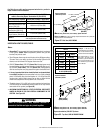
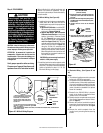
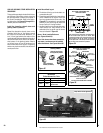
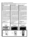
Junction Box
Tab Intact
Tab
Broken
Plug blower
into this
receptacle
neerG - dnuorG
* Wall-mounted
ON/ OFF Blower
Switch or Variable
Speed Control Switch.
Blower
Ground
etihW - lar
t
ueN
120 VAC - Black
Green
Ground
Screw
White
Green
Neutral
Side of
Receptacle
Hot
Side of
Receptacle
Red
Black
J-BOX WIRING FOR
WALL SWITCH
BLOWER CONTROL
Figure 46
IMPORTANT NOTE
The gas valve OFF/ON switch is
shown in Figure 46 on Page 26. It
is integral with the gas valve and
should be set to the ON position.
5. Install a field-provided strain relief in the
cabinet knockout opening for the protection
of the power supply wires.
6. Connect the power supply wires to the
receptacle as shown in Figure 46 on Page
26.
7. Connect the ground supply wire to the green
wire attached to the outlet receptacle’s
green ground screw.
8. Wire and install the outlet receptacle to
junction box. Next, install into the chosen
corner of the control compartment as shown
in Figure 45.
9. After the receptacle/junction box wiring is
complete, install the field-provided metal
junction box cover plate (see Figure 45).
Note: The supplied 15 feet of 2 conductor
wire has one end of each conductor con-
nected to the gas valve circuit and the other
end of each conductor placed loose on top
of the appliance.