


3
NOTE: DIAGRAMS & ILLUSTRATIONS NOT TO SCALE.
Carbon Monoxide Poisoning: Early signs of
carbon monoxide poisoning are similar to the
flu with headaches, dizziness and/or nausea. If
you have these signs, obtain fresh air immedi-
ately. Turn off the gas supply to the appliance
and have it serviced by a qualified profes-
sional, as it may not be operating correctly.
Maximum manifold pressure is 3.5 in. w.c.
(0.87 kPa) for natural gas and 10 in. w.c.
(2.49 kPa) for LP/Propane gas.
Do not use these appliances if any part has been
under water. Immediately call a qualified, profes-
sional service technician to inspect the appliance
and to replace any parts of the control system and
any gas control which have been under water.
Ne pas se servir de cet appareil s'il a été plongé
dans l'eau, complètement ou en partie. Appeler
un technicien qualifié pour inspecter l'appareil et
remplacer toute partie du système de contrôle et
toute commande qui ont été plongés dans l'leau.
Test gage connections are provided on the
front of the millivolt gas control valve (identi-
fied OUT for the manifold side and IN for inlet
pressure. A ¹⁄₈" NPT test gage connection is
provided on the electronic gas control valve
adjacent to the outlet to the main burner.
Minimum inlet gas pressure to these appliances
is 5.0 inches water column (1.24 kPa) for natural
gas and 11 inches water column (2.74 kPa) for
propane for the purpose of input adjustment.
Maximum inlet gas supply pressure to these
appliances is 10.5 inches water column (2.61
kPa) for natural gas and 13.0 inches water
column (3.23 kPa) for propane.
The appliance must be isolated from the gas
supply piping system (by closing its individual
manual shut-off valve) during any pressure test-
ing of the gas supply piping system at test
pressures equal to or less than ¹⁄₂ psig (3.5 kPa).
The appliance and its individual shut-off valve
must be disconnected from the gas supply
piping system during any pressure testing of
that system at pressures in excess of ¹⁄₂ psig
(3.5 kPa).
These appliances must not be connected to a
chimney or flue serving a separate solid fuel
burning appliance.
Any safety guard or screen removed for servic-
ing the appliance must be replaced prior to
operating the appliance.
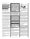
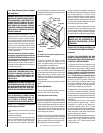
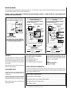
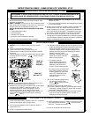
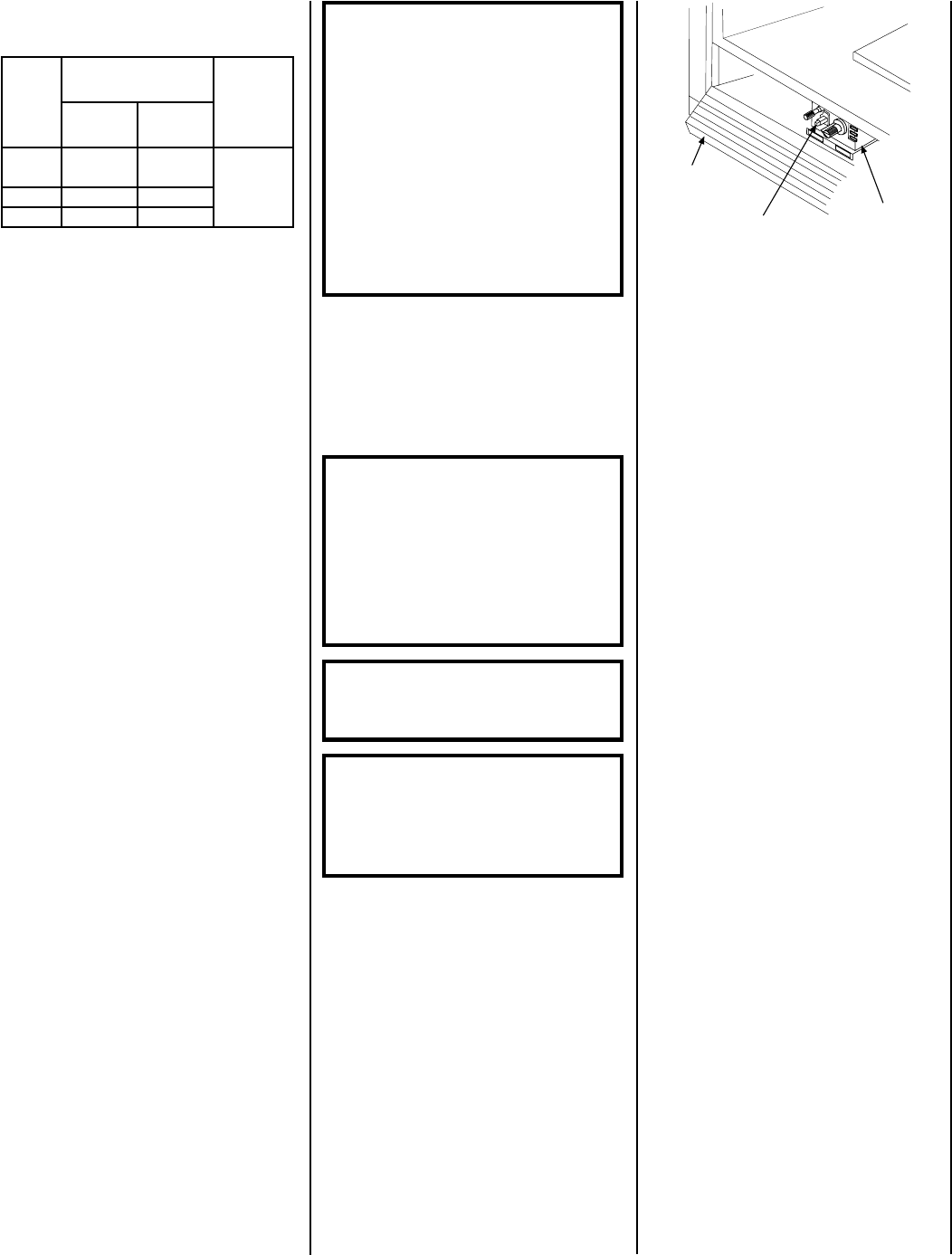
Gas Controls/Control Compartment Access
The gas controls can be found behind the control
compartment access panel. To open the control
compartment access panel, actuate the spring-
loaded magnetic catches securing the panel, by
gently depressing the outer top corners of the
panel until the catches "pop" the door free, allow-
ing it to swing out and down to open.
Operation of millivolt and electronic gas con-
trol systems are different. Before lighting and
operating your appliance determine if you have
a millivolt or electronic appliance. See
Figure 1
for access to the control compartment.
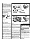
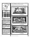
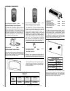
Millivolt appliances will be fitted with the gas
control valve shown in
Figure 3 (SIT) or Figure
4 (Honeywell) on page 4
. Appliances with
electronic systems will be fitted with the elec-
tronic valve shown in
Figure 2 on page 4
.
Familiarize yourself with the gas control valve
that your appliance uses.
OPERATION AND CARE OF YOUR
APPLIANCE
Appliance operation may be controlled through
a remotely located optional wall switch. Sepa-
rate switches may provide independent control
for the remote controlled fireplace operation
(optional equipment).
In lieu of remote or remote wall switch opera-
tion, the appliance must be operated directly
through the controls located on the front of the
valve located within the control compartment
which is located behind the control compart-
ment access panel below the appliance front
glass enclosure panel. See
Figure 1.
WARNING: DO NOT PLACE CLOTH-
ING OR OTHER FLAMMABLE MATERI-
ALS ON OR NEAR THIS APPLIANCE.
AVERTISSEMENT: SURVEILLER LES
ENFANTS. GARDER LES VÊTEMENTS,
LES MEUBLES, L'ESSENCE OU AUTRES
LIQUIDES À VAPEUR INFLAMMABLES
LOIN DE L'APPAREIL.
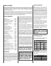
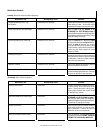
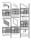
The following table shows the units' orifice size
for the elevations indicated.
WARNING: CHILDREN AND ADULTS
SHOULD BE ALERTED TO THE HAZARDS
OF HIGH SURFACE TEMPERATURES. USE
CAUTION AROUND THE APPLIANCE TO
AVOID BURNS OR CLOTHING IGNITION.
YOUNG CHILDREN SHOULD BE CARE-
FULLY SUPERVISED WHEN THEY ARE IN
THE SAME ROOM AS THE APPLIANCE.
WARNING: FAILURE TO COMPLY
WITH THE INSTALLATION AND OP-
ERATING INSTRUCTIONS PROVIDED
IN THIS DOCUMENT WILL RESULT IN
AN IMPROPERLY INSTALLED AND OP-
ERATING APPLIANCE, VOIDING ITS
WARRANTY. ANY CHANGE TO THIS
APPLIANCE AND/OR ITS OPERATING
CONTROLS IS DANGEROUS. IM-
PROPER INSTALLATION OR USE OF
THIS APPLIANCE CAN CAUSE SERI-
OUS INJURY OR DEATH FROM FIRE,
BURNS, EXPLOSION OR CARBON
MONOXIDE POISONING.
Figure 1
Control Compartment Access -
Millivolt Control Valve Shown
Millivolt Appliances -
To light millivolt appliances refer to the detailed
lighting instructions found on
page 12 (En-
glish) and page 13
(French)
. Millivolt appli-
ance lighting instructions may also be found
on the pull-out lighting instruction labels
attached to the gas control valve. Refer to
Figure 2 (SIT), 3 (Honeywell) on page 4
for
the location of the piezo ignitor.
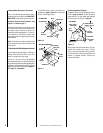
Millivolt appliances may be fitted with an optional
burner ON/OFF Rocker Switch. The optional ON/
OFF Rocker switch will be installed in the bracket
just beneath the gas control valve. Once the pilot
is lit, the ON/OFF rocker switch will control the
appliance ON/OFF operation. To operate: Toggle
the switch between its ON and OFF positions.
If your millivolt appliance is equipped with an
optional remote wall switch or remote control
kit and the pilot is lit, the appliance main burner
may be turned on and off with the wall switch
or remote control.
,DB
,T-DB
R-DB
seireS
eziSecifirO
noitavelE
teeF
)sreteM(
.taN.porP
53.ni090.045#
0054-0
)0731-0(
0463#25#
5433#.ni560.0
Piezo Ignitor
Honeywell Millivolt
Gas Valve Shown
Control
Compartment
Access Panel