


NOTE: DIAGRAMS & ILLUSTRATIONS NOT TO SCALE.
7
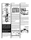
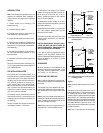
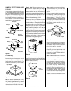
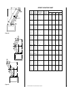
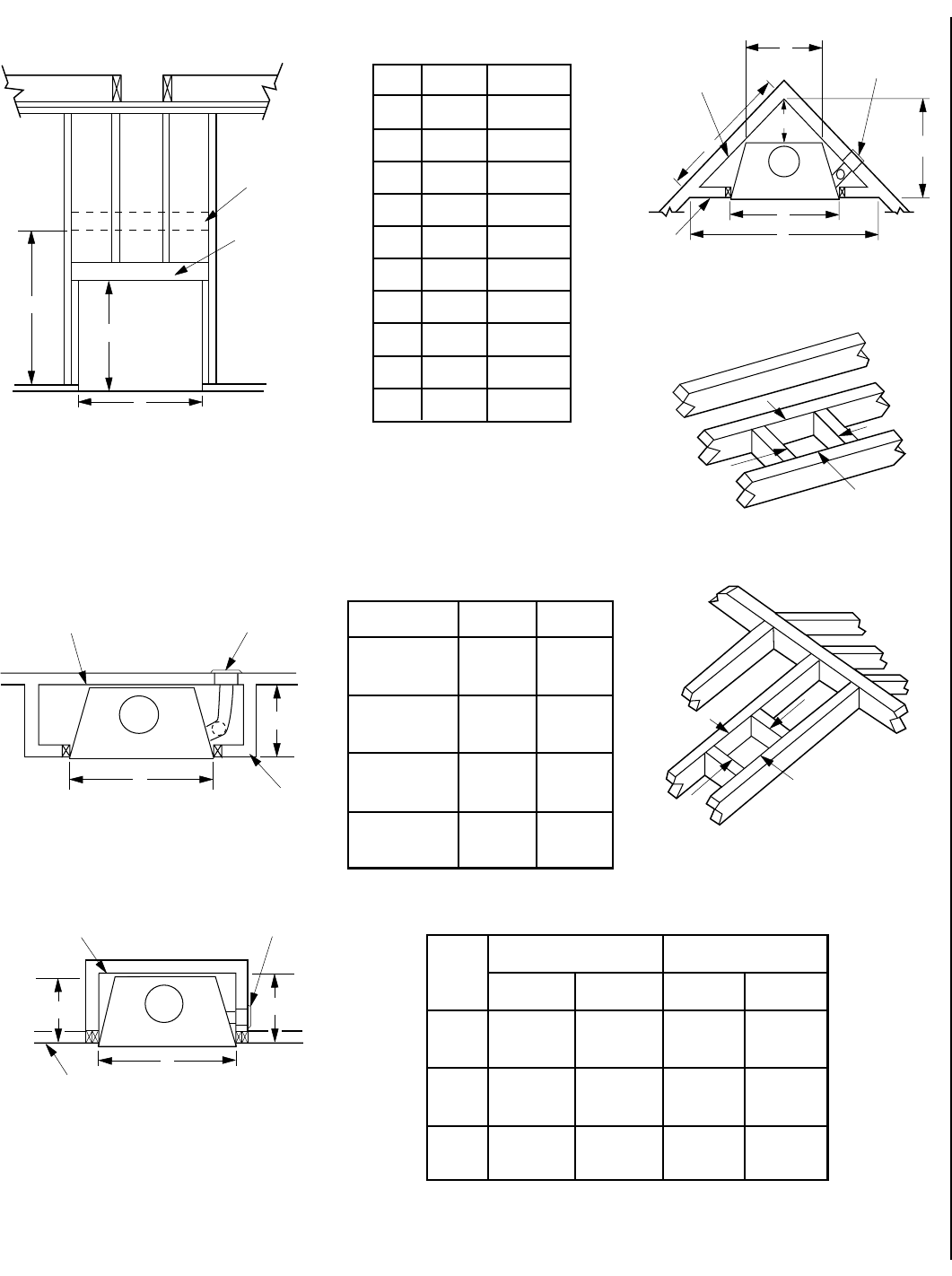
FRAMING SPECIFICATIONS
Figure 11
Figure 12
Figure 13
Figure 14
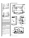
Framing Dimensions
A 42-1/4" 1073 mm
B
1 37-1/2" 953 mm
B2 54-1/2" 1384 mm
C 28-3/4" 730 mm
D 15-3/8" 391 mm
E 70" 1778 mm
F 35" 889 mm
G 20-5/8" 524 mm
H 19-5/8" 498 mm
J 49-1/2" 1257 mm
K 8" 203 mm
Note: All framing dimensions calcu-
lated for 1/2" dry wall at the fireplace
face. If sheathing the chase or finish-
ing with other thickness materials,
calculations will need to be made.
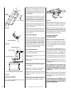
Header
Fireplace Framing
B
1
A
(See Note)
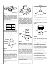
*Note: When Framing With 6” Studs Header Must
Be 17” (432mm) Higher. Use Security Chimney’s
OR15 Offset/Return Elbow To Recess The Chimney
Back 2 1/2” (64mm). Flat Frame Down To A False
Header At (B
1
). Maintain Required Clearance To
Chimney At All Times.
*B
2
A
Outside Chase
G
H
Back Wall of Chase/Enclosure
Including Finising Materials
if any
Rough
Framing Face
(Unfinished Shown)
FOAK
Combustion
Air Kit - Optional
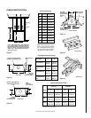
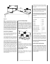
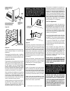
Corner Installation
J
D
A
E
F
Back Wall of
Chase/Enclosure
Including Finising
Materials
if any
Rough
Framing Face
(Unfinished Shown)
FOAK Combustion
Air Kit - Optional
C
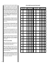
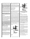
Figure 15
Figure 16
Framing Dimensions for Roof
FTF8 at 1" FTF8 at 2"
Pitch C D* C D*
0/12 14-1/2" 14-1/2" 16-1/2" 16-1/2"
(368 mm) (368 mm) (419 mm) (419 mm)
6/12 14-1/2" 17" 16-1/2" 19"
(368 mm) (442 mm) (419 mm) (483 mm)
12/12 14-1/2" 21-1/2" 16-1/2" 23-1/2"
(368 mm) (546 mm) (419 mm) (579 mm)
* Perpendicular to roof ridge
A
B
Ceiling Framing
C
D
Roof Framing
Framing Dimensions for Ceiling
Flue Type A B
FTF8 Vertical 14-1/2" 14-1/2"
(368 mm) (368 mm)
FTF8 Vertical 16-1/2" 16-1/2"
at 2" (419 mm) (419 mm)
FTF8 Offset 30° 14-1/2" 25"
(368 mm) (635 mm)
FTF8 Offset 30° 16-1/2" 27"
at 2" (419 mm) (686 mm)
A
G
Inside Chase
Back Wall of Chase/Enclosure
Including Finising Materials if any
Rough
Framing Face
(Unfinished Shown)
FOAK Combustion
Air Kit