


NOTE: DIAGRAMS & ILLUSTRATIONS NOT TO SCALE.
6
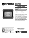
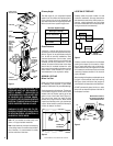
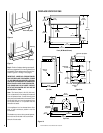
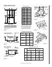
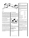
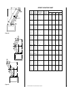
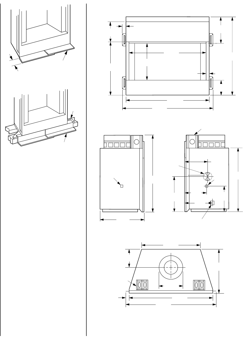
FIREPLACE SPECIFICATIONS
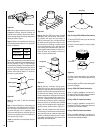
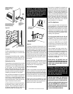
Figure 10
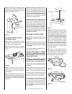
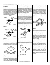
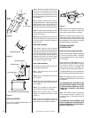
Blocking
Metal Safety Strips
Figure 8
Figure 9
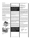
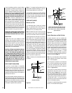
Step 3. Refer to fireplace drawings and specifi-
cations on pages 6 and 7 for framing dimensions
and details. Frame appliance enclosure as illus-
trated in
Figures 11 through 14
on page 8.
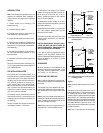
IMPORTANT: UNDER NO CIRCUMSTANCES
CAN THE FIREPLACE TOP SPACERS (
FIGURE
10
) BE REMOVED OR MODIFIED, NOR MAY
YOU NOTCH THE HEADER TO FIT AROUND OR
BE INSTALLED LOWER THAN THE SPACERS.
THE HEADER MAY BE IN DIRECT CONTACT
WITH THE TOP SPACERS BUT MAY NOT BE
SUPPORTED BY THEM.
Note: The framed depth, 20-5/8" (524 mm)
from a framed wall, must always be measured
from a finished surface. If a wall covering such
as drywall is to be attached to the rear wall, then
the 20-5/8" (524 mm) must be measured from
the drywall surface. It is important that this
dimension be exact.
If the appliance is to be elevated above floor
level, a solid continuous platform must be
constructed.
The header may rest on the top metal spacers,
but must not be notched to fit around them.
Consult all local codes.
Metal Safety Strips
1-1/2"
40"
(1016 mm)
Front (BC Model Shown)
37"
(940 mm)
7-3/16"
(183 mm)
36"
(914 mm)
2"
(51 mm)
12-1/2"
(318 mm)
37"
(940 mm)
20-1/4"
(514 mm)
Left Side
Right Side
40"
(1016 mm)
27-1/4"
(692 mm)
20-1/4"
(514 mm)
7-13/16"
(198 mm)
Top View
Gas Line
Access
Combustion
Air Inlet
20-3/16"
(513 mm)
9-7/8"
(251 mm)
17-3/8"
(441 mm)
32"
(813 mm)
9-5/8"
(244 mm)
7-1/2"
(191 mm)
27-7/8"
(708 mm)
Appliance Top Spacer
Appliance
Top Spacer
Junction
Box
Gas Line
Access
43"
(1092 mm)
43"
(1092 mm)
1-1/2"
(38 mm)
9-1/16"
(230 mm)
12-7/8"
(327 mm)
9-3/16"
(233 mm)
1-1/2"
(38 mm)