


Page 34 SMC Series Chillers
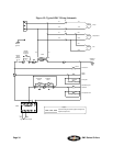
Figure 15: Typical SMC Wiring Schematic
1T1T
1FU1FU
1
X111
Jumper
Remote
interlock
by others
1S-1LT
1
3
1C
1
41615
2C
Pump
starter
Condensing unit
contactor
G
1S-1LT
G
"Power On"
ON/OFF
1L1
1L2
1L1
1L2
1L11L2
2
Control
power
1PS 2PS
11
1CNTL
RED
(-)
YEL
(+)
Type K Thermocouple
Subpanel
ground
1C
1T1
1T2
1MTR
Pump
2C
2T1
2T2
Compressor
230V
115V
Jumper
1
6
1
2
1
7
1
3
1
8
1
4
1
9
1
5
1
10
"Low Refrig
Pres"
G
3LT
R
"Hi Refrig
Pres"
G
4LT
R
ground
Earth
Fan
3T2
3T1
2MTR
3MTR
G
5LT
G
G
2LT
G
"Pump On"
"Compressor On"
Legend
Customer wiring/Customer-supplied components
Optional components
2