


20
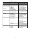
1. Burner orifi ce too small.
1.
Irregular orifi ce causing whistle or resonance.
2. Excessive gas input.
1. Clogged main burners.
2. Misaligned orifi ces.
3. Insuffi cient combustion air.
4. Possibly over fi red.
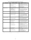
1. Blocked venting.
2. Insuffi cient combustion air.
3. Blocked heat exchanger.
4. Air leak into combustion chamber
or draft hood.
1. Shut off gas supply immediately!
2. Leaking gas test port on valve.
3. Blocked heat exchanger.
4. Blocked draft hood.
5. Negative pressure in the building.
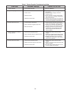
1. Improper ground.
2. Bad or broken spark cable.
3. Faulty control.
4. Pressure regulator set too low.
5. Main burner orifi ces dirty.
6. Improper venting.
1. Gas supply is off.
2. No power supply to unit.
3. Thermostat not calling.
4. Defective high limit.
5. Defective drafter prove switch.
6. Loose wiring.
7. Improper ground.
8. Improper thermostat or transformer wiring.
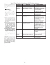
1. Improper venting.
2. Unit under fi red.
3. Building too cold.
Table 6 - Tubular Propeller Troubleshooting Guide
1.
Check with local gas supplier for proper orifi ce
size and replace. Refer to “Operation”.
1. Replace orifi ce.
2. Test and reset manifold pressure.
1. Clean main burner ports.
2. Replace manifold assembly.
3. Insuffi cient combustion air.
4. Check gas input and manifold pressures.
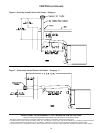
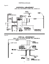
1. Clean Flue. Refer to “Installation”.
2. Clean combustion air inlet openings.
3. Clean heat exchanger. Refer to “Installation”.
4. Determine cause and repair accordingly.
1. Inspect all gas piping and repair.
2. Check to ensure gas test ports are seated.
3. Clean heat exchanger/fl ue.
4. Clean fl ue collector.
5. See “Installation”.
1. Check grounding wires and spark bracket
connections.
2. Inspect spark cable connections and cuts.
3. Check to ensure spark is energized after
pre purge period.
4. Test and reset manifold pressure refer to
“Operations”.
5. Clean or replace orifi ces.
6. Refer to “Installation”.
1. Open all manual valves “check for leaks”.
2. Turn on power supply, check fuses and
replace if bad.
3. Turn up thermostat, Check for 24v on
terminals R and W1 on terminal strip.
4. Check switch for continuity if open with no
heat present, replace.
5. Check switch operation to ensure
switch closes after draftor purge period.
If it does not make/check tubing
connections/ blockage.
6. Check all wiring per diagram.
7. Check all ground wires and connections.
8. Check both, for wiring according to diagram;
check for 24V at gas valve terminals during
trial for ignition period if present and valve
does not open. Replace valve.
1. Refer to “Installation, Venting”.
2. Check gas supply pressures to unit. Refer
to “Installation”.
3. Refer to “Installation”.
A. Flame pops back.
B. Noisy Flame.
C. Yellow tip fl ame (some yellow
tipping on LP gas is permissible).
D. Floating fl ame.
E. Gas odor.
F. Delayed ignition.
G. Failure to ignite.
H. Condensation.
SYMPTOMS
POSSIBLE CAUSE(S) CORRECTIVE ACTION