


17
OPERATION
POWER VENTED PROPELLER UNITS
DIRECT SPARK IGNITION
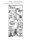
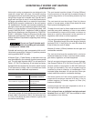
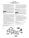
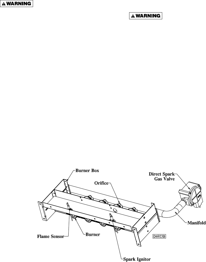
EXPLANATION OF CONTROLS (See Figure 10):
1. The unit heater is equipped with a power vent system
that consists of a power venter motor and blower,
pressure switch, and sealed fl ue collector in place of
the conventional draft diverter.
2. The power venter motor is energized by the room
thermostat through the integrated control board when
a demand for heat is sensed. The pressure switch
measures the flow through the vent system and
energizes the direct spark ignition system beginning
the pre-purge timing when the fl ow is correct.
The pressure switch MUST NOT be
bypassed. The unit MUST NOT be fi red unless the
power venter is operating. An unsafe condition
could result.
3. The direct ignition system consists of an ignition
control module and a gas valve. When the pre-
purge period ends, the spark ignition system is
energized, and the gas valve opens to supply gas
to the burners. When the thermostat is satisfi ed, the
vent system is de-energized and the valve closes to
stop the fl ow of gas to the unit.
4. The limit switch interrupts the fl ow of electric current
to the control board, interrupting the fl ow of gas to the
gas valve if the unit heater becomes overheated.
5. Once the thermostat is satisfi ed, or the limit switch
interrupts the fl ow of electric current to the control
board, the unit will begin a post-purge period. When
the post-purge period ends, the power venter motor
is de-energized.
6. The fan operation is delayed 30 seconds once the
thermostat is closed, and continues operation for 30
seconds after the thermostat opens.
NOTICE: The start-up fan delay must not exceed 30
seconds from a cold start.
7. The wall thermostat, supplied optionally, is a
temperature sensitive switch that operates the vent
and ignition system to control the temperature of
the space being heated. The thermostat must be
mounted on a vertical, vibration-free surface free
from air currents and in accordance with the furnished
instructions (also refer to Electrical Section).
START-UP (Also refer to lighting instruction plate
equipped on the unit)
1. Open the manual gas valve in the gas supply line to
the unit heater. Loosen the union in the gas line to
purge it of air. Tighten the union and check for leaks.
Never use an open flame to
detect gas leaks. Explosive conditions may
exist which could result in personal injury or
death.
2. Open the manual valve on the unit heater.
3. Turn ON the electrical power.
4. The unit should be under the control of the thermostat.
Turn the thermostat to the highest point and determine
that the power venter motor starts and the burners
ignite. Turn the thermostat to the lowest point and
determine that the power venter motor shuts off and
the burners are extinguished.
5. Turn the thermostat to the desired position.
6. See Gas Input Rate and Adjustments sections.
SHUT DOWN
1. Turn the valve selector lever to the “OFF” position.
2. Turn off the electricity.
3. To relight, follow “start-up” instructions.
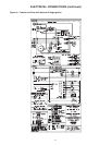
See Figures 10-17 for parts/identifi cation.
Figure 10