


12
VERTICALLY VENTED UNIT HEATERS
(CATEGORY I)
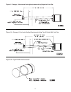
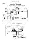
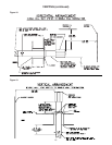
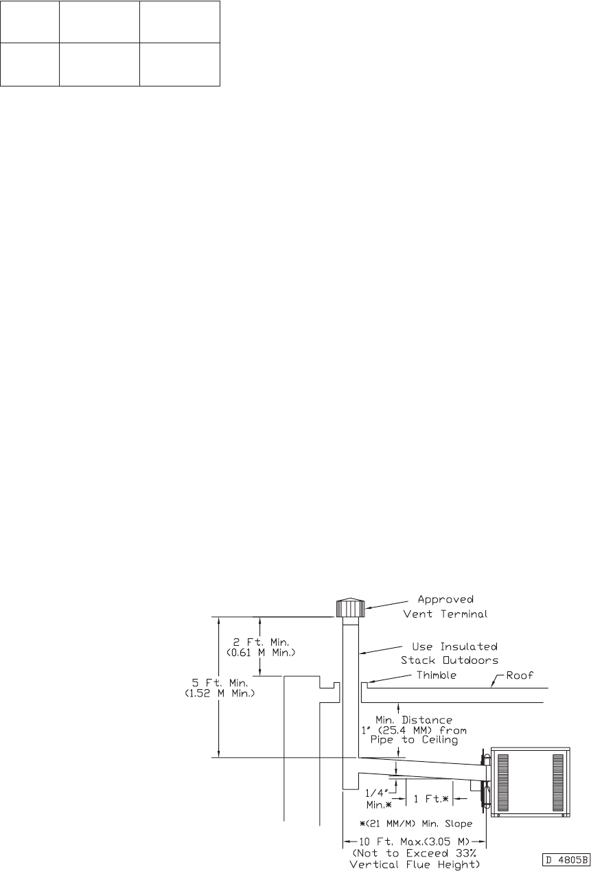
Observe the following precautions when venting the unit:
The unit heater shall be connected to a factory built
chimney or vent complying with a recognized standard,
or a masonry or concrete chimney lined with a lining
material acceptable to the authority having jurisdiction.
Venting into an unlined masonry chimney is
prohibited.
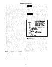
1. Use flue pipe of the same size as the flue
connections on the gas unit heater, 4 inch (102mm).
All heaters must be vented with UL Listed Type B
vent, or single wall pipe.
2. Provide as long a vertical run of flue pipe at the gas
unit heater as possible. A minimum of 5 feet (1.5m)
of vertical flue is required. The top of the vent pipe
should extend at least 2 feet (0.61m) above the
highest point on the roof. Install a weather cap over
the vent opening.
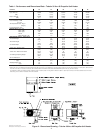
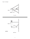
3. Slope horizontal runs upward from the gas unit
heater at least 1/4-inch per foot (21mm/m) minimum.
Horizontal runs should not exceed 33% of the
vertical height of the vent pipe, or chimney, above
the flue pipe connection, up to a maximum length
of 10 feet (3m). Horizontal portions of the venting
system shall be supported at maximum intervals of
4 feet (1.22m). (See Figure 12)
4. Use as few elbows as possible.
5. Tape flue pipe joints with high temp, RTV or foil
face tape.
6. Avoid running vent pipe through unheated spaces.
7. When this cannot be avoided, insulate the pipe to
prevent condensation of moisture on the walls of
the pipe. Insulate vent pipe runs longer than 10 feet
(3m). Insulation should be a minimum of 1/2 inch
(12.7mm) thick foil faced fiberglass, 1-1/2# density
insulation.
8. Do not damper the flue piping. Failure to open such
a damper prior to operating the gas unit heater will
result in the spillage of flue gas into the occupied
space.
9. Avoid installing units in areas under negative
pressure due to large exhaust fans or air
conditioning. When required, a flue vent fan should
be installed in accordance with the instructions
included with the fan.
10. Vent connectors serving Category I and Category
II heaters shall not be connected into any portion of
mechanical draft systems operating under positive
pressure.
11. Also refer to Figures 17 and 19 for additional
requirements.
Figure 12
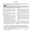
VENTING
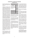
ANSI now organizes vented
appliances into four categories.
Category
I
Includes non-condensing
appliances with negative vent
pressure, like the traditional
atmospheric unit heater.
Category
II
Groups condensing appliances
with negative vent pressure.
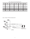
Venting Categories
Non
Condensing Condensing
Negative
Vent III
Pressure
Positive
Vent III IV
Pressure
Category
III
Appliances are non-condensing
and operate with a positive vent
pressure.
Category
IV
Covers condensing appliances
with positive vent pressure.
NOTICE: Category II and IV do
not apply to equipment specified
within this manual.