


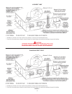
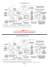
5
The temperature may be adjusted from 80°F/27°C to 180°F/82°C.
The thermostat was adjusted to 120°F/49°C before the heater
was shipped from the factory. It is recommended that lower water
temperatures be used to avoid the risk of scalding. It is further
recommended, in all cases, that the water temperature be set for the
lowest temperature which satises your hot water needs. This will
also provide the most energy efcient operation of the water heater
and minimize scale formation.
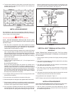
WATER TEMPERATURE SETPOINT ADJUSTMENT
PROCEDURE
CAUTION
THE TEMPERATURE OF THE WATER AT THE TANK OUTLET
MAY NOT CORRESPOND TO THE TEMPERATURE SETPOINT
PROGRAMMED IN THE CONTROLLER. THE USER CAN EASILY
CHANGE THE TEMPERATURE SETPOINT AT ANY TIME BY USING
THE FOLLOWING PROCEDURE. IN ALL CASES, INPUT POWER
MUST BE APPLIED TO THE CONTROLLER TO PERFORM ANY
PROGRAMMING OPERATIONS.
The Operating Set Point of this water heater determines the regulated
temperature for the water in the tank. This parameter is adjusted in the
Temperature menu. Items in this menu allow you to monitor different
temperature readings in the tank along with adjusting the Operating
Set Point and Differential. To change the current programmed
temperature setpoint value, see OPERATION section for details.
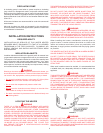
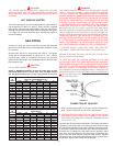
Figure 1 shows the approximate time-to-burn relationship for normal
adult skin. Short repeated heating cycles caused by small hot water
uses can cause temperatures at the point of use to exceed the
thermostat setting by up to 20°F (11C°). If you experience this type
of use, you should consider using lower temperature settings to
reduce scald hazards.
Temperature Time to Produce 2nd & 3rd
Setting Degree Burns on Adult Skin
180°F / 82°C Nearly instantaneous
170°F / 77°C Nearly instantaneous
160°F / 71°C About 1/2 second
150°F / 66°C About 1-1/2 seconds
140°F / 60°C Less than 5 seconds
130°F / 54°C About 30 seconds
120°F / 49°C More than 5 minutes
FIGURE 1.
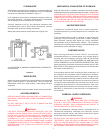
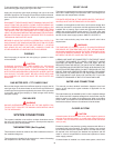
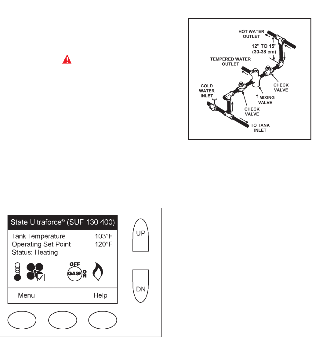
Valves for reducing point-of-use temperature by mixing cold
and hot water are available (see Figure 2). Also available
are inexpensive devices that attach to faucets to limit hot
water temperatures. Contact a licensed plumber or the local
plumbing authority.
FIGURE 2.
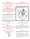
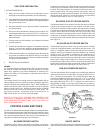
HIGH LIMIT SWITCH (E.C.O.)
The top immersion well of the dual bulb controller also contains
the high limit (energy cutoff) sensor. The high limit switch interrupts
the main burner gas ow should the water temperature reach
approximately 202°F/94°C. Should the high limit switch activate,
the water temperature must drop below 140°F/60°C before the
controller can be reset. The following is a possible reason for high
limit switch operation.
• A malfunction in the thermostatic controls would allow the gas
valve to remain open causing water temperature to exceed the
thermostat setting. The water temperature would continue to
rise until high limit switch operation.
Contact your dealer or servicer if continued high limit switch
operation occurs.
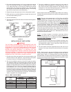
DISHWASHING MACHINE REQUIREMENT
All dishwashing machines meeting the National Sanitation
Foundation requirements are designed to operate with water
flow pressures between 15 and 25 pounds per square inch
(103 Kpa and 173 Kpa). Flow pressures above 25 pounds per
square inch (173 Kpa), or below 15 pounds per square inch
(103 Kpa), will result in improperly sanitized dishes. Where
pressures are high, a water pressure reducing or flow regulating
control valve should be used in the 180°F (82°C) line to the
dishwashing machine, and should be adjusted to deliver water
between these limits.
The National Sanitation Foundation also recommends
circulation of 180°F (82°C) water. Where this is done, the
circulation should be very gentle so that it does not cause
any unnecessary turbulence inside the water heater. The
circulation should be just enough to provide 180°F (82°C)
water at the point of take-off to the dishwashing machine.
Adjust flow by means of the plug cock in the circulating line.
(See installation diagrams.)