


37
Checking these four (4) items rst will often result in a timely solution
to the service call.
WARNING
JUMPING OUT COMPONENTS AND/OR CIRCUITS DURING
TROUBLESHOOTING CAN CAUSE SERIOUS PROBLEMS WITH
THE UNIT’S OPERATING SEQUENCE AND IGNITION SAFETY.
IF YOU DO NOT HAVE THE PROPER TEST EQUIPMENT, I.E. A
VOLT-OHM METER AND A MICROMETER, DO NOT ATTEMPT TO
TROUBLESHOOT OR REPAIR STATE EQUIPMENT.
ALTERING THE CONTROLLER AND/OR CONTROLLER WIRING
IN ANY WAY COULD RESULT IN INTERNAL DAMAGE TO THE
MODULE CIRCUITS, POSSIBLY ALTERING THE IGNITION
SEQUENCE ALLOWING GAS VALVES TO OPEN BEFORE THE
HOT SURFACE IGNITER IS UP TO IGNITION TEMPERATURE.
NOTE: ANY BYPASS OR ALTERATION OF THE UNITS SAFETIES
WILL RESULT IN VOIDING THE APPLIANCE WARRANTY.
Before performing any troubleshooting familiarize yourself with the
particular appliance.
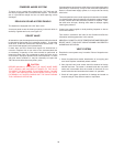
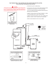
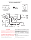
Refer to the SEQUENCE OF OPERATION and the connection
diagram located on page 16 before continuing.
Make sure the appliance is connected to a 120V AC power supply,
manual gas valve is in the ON position, and all electrical connections
are secure before continuing to troubleshoot this appliance.
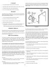
CAUTION
THE WATER HEATER IS POLARITY SENSITIVE. BEFORE APPLYING
ELECTRICITY TO THIS HEATER BE CERTAIN THAT SUPPLY NEUTRAL
WIRE TO GROUND CHECK INDICATES ZERO VOLTAGE.
MOTOR WILL NOT RUN
1. Conrm 120V AC. Also, to verify correct polarity, check for 120 V
AC between hot supply and ground. If there is no voltage, check
for a loose connection.
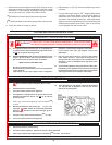
2. For SUF 130 400, a VFD (Variable Frequency Drive) is used. "rdy"
(stands for ready) will be shown on display in standby heating
mode. "155" (155 output Hz) shall be shown on VFD display during
heater running for SUF 130-400 model. Any other display on the
VFD indicates a faulty VFD of wrong speed reference, call State
Tech Support for assistance.
MOTOR RUNS, PREPURGE TIME ELAPSES BUT
MAIN FLAME NOT ESTABLISHED
1. Check to see if main manual gas valve is open.
2. Check for a loose connection at the transformer, or a defective
transformer.
3. Check for a loose connection at the gas valve.
4. Check for open pressure switches or open reset button. Check for
blockage in the intake and exhaust venting or at the vent hoods.
If no blockage is found, check vinyl tubing for cuts or crimps. If
this tubing is damaged it must be replaced. If these steps do not
eliminate the problem, replace the pressure switches.
5. Check to see if there is resistance across the igniter terminal with
an OHM meter. If there is no continuity, the igniter is broken and
should be replaced.
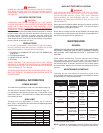
If the igniter appears to function properly, then verify that the
inlet pressure is 11.0" Natural Gas (2.74 kPa). The gas valve
supplied on this appliance is not designed to open against a
higher pressure. At this time also check that the inlet pressure
is not lower than the minimal gas supply pressure, as shown
in Table 4: that is, for Natural Gas, 5.2" (1.29 kPa) W.C. If the
inlet pressure is not within these limits then adjust the supply
pressure accordingly.
If the inlet pressure falls within the allowable limits, then verify
that the manifold pressure, when the gas is fully open, with the
heater running, is as called out in Table 4: that is, for Natural
Gas, 4.0" (0.996 kPa) W.C. If the manifold pressure is not correct
then adjust accordingly. See ADJUSTMENT PROCEDURE
in OPERATING INSTRUCTIONS selection, page 19, for the
manifold pressure adjustment procedure.
6. If the inlet and manifold pressures are within the limits
specified in step 5, then reset the appliance. Verify 24V AC at
the gas valve during the three (3) second ignition trial, after
the igniter reaches operating temperature. If 24V AC at the
gas valve is not seen during this period, the controller must
be replaced.
If there is 24V AC at the gas valve during the four second
ignition trial and the manifold pressure does not increase
above 0" W.C. then verify that the manual gas control valve
is in the “ON” position (see page 20). If the valve is in the
“ON” position and the previous voltage and gas pressure
conditions are met, then the gas valve is defective and must
be replaced.
MOTOR RUNS, BURNER LIGHTS MOMENTARILY,
THEN LOCKS OUT
1. Reset the appliance two more times to ensure that all of the air
has been purged from the gas line.
2. If the burner lights momentarily but does not sustain ignition,
verify that the inlet pressure is not greater than 11.0" (2.74
kPa) W.C. or lower than the minimal gas supply pressure, as
shown in Table 4: that is, for Natural Gas, 5.2" (1.29 kPa) W.C.
pressure. Also, the manifold pressure should rise during the
three (3) second trial for ignition to the manifold pressure value
for the individual unit listed in Table 4: that is, for Natural Gas,
4.0" (0.996 kPa) W.C. If the manifold pressure is not correct
then adjust accordingly. See ADJUSTMENT PROCEDURE in
OPERATING INSTRUCTIONS section, page 19, for the manifold
pressure adjustment procedure.
3. Check for the reversed polarity in the supply wiring. This controller
is polarity sensitive. If the hot and neutral supply wires are
reversed, the controller will not sense ame. Reverse the supply
wires and try to re the unit.