


ULTRAFORCE COMMERCIAL GAS WATER HEATER
SUF 120 thru 400 SERVICE HANDBOOK
State Water Heaters – Technical Training Department 4 Ashland City, Tennessee © 2009
Servicing should only be performed by a Qualified Service Agent 198152-002
GENERAL INFORMATION
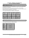
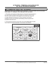
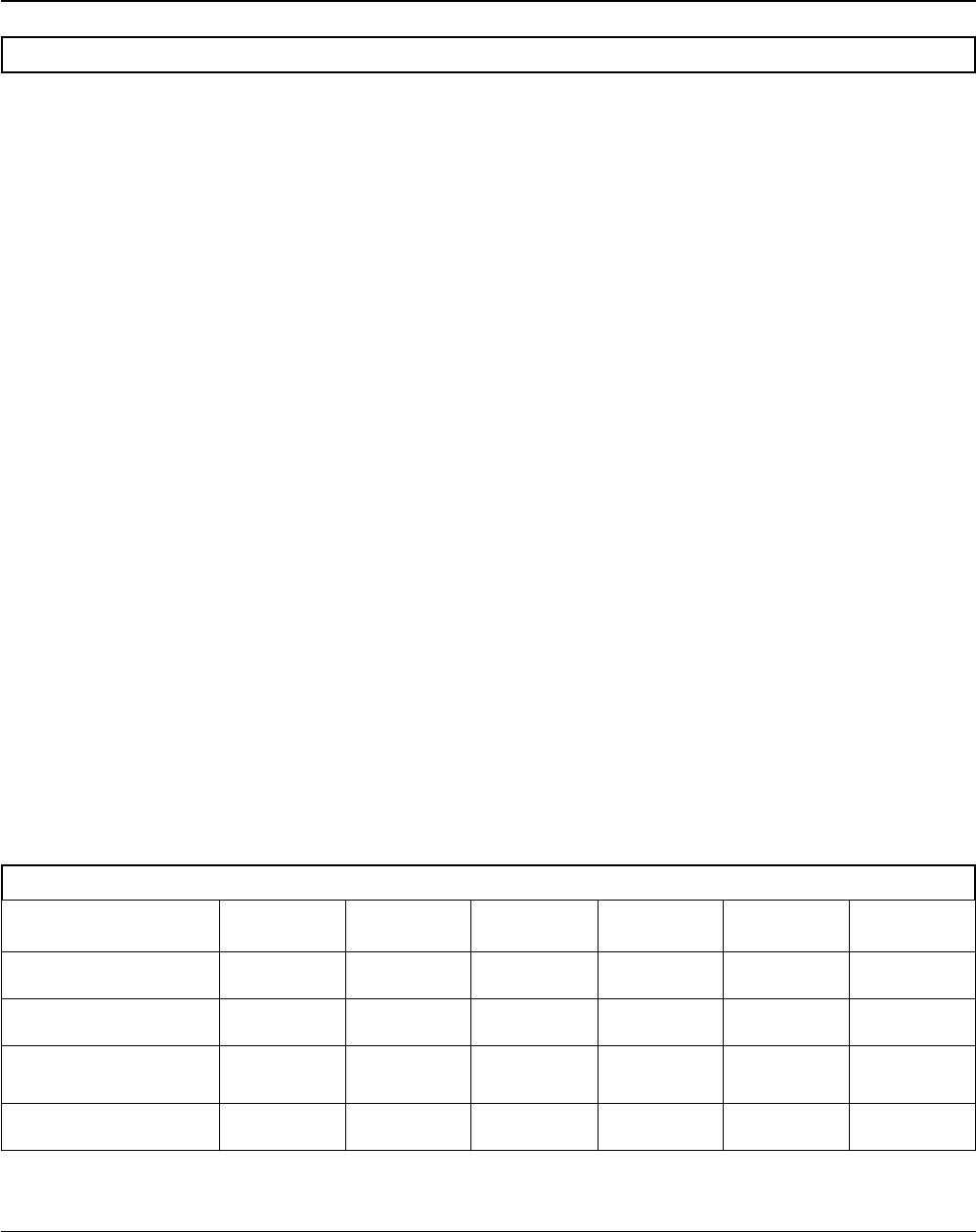
GAS PRESSURE SPECIFICATIONS
INSTALLATION REQUIREMENTS FOR THE
COMMONWEALTH OF MASSACHUSETTS
For al l side w all terminated, hor izontally vented
power vent, direct vent, and power direct vent gas
fueled w ater heat ers installed i n ev ery dwelling,
building or structure used in whole or in part for
residential pur poses, including t hose ow ned or
operated by the Commonwealth and where the side
wall exhaust vent termination is less than seven (7)
feet above finished grade in the area of the venting,
including but not limited to decks and porches, the
following requirements shall be satisfied:
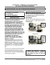
INSTALLATION OF CARBON MONOXIDE
DETECTORS
At the time of installation of the side wall horizontal
vented gas fueled equipment, the installing plumber
or gas fitter shall observe that a hard wired carbon
monoxide detector with an alarm and battery back-
up is installed on the floor level where the gas
equipment is t o b e i nstalled. In add ition, t he
installing plumber or gas fitter shall observe that a
battery operated or har d wired carbon monoxide
detector w ith an al arm i s i nstalled on eac h
additional level of the dwelling, building or structure
served by the sidewall horizontal vented gas fueled
equipment. It s hall b e the re sponsibility of the
property owner to secure the services of qualified
licensed pr ofessionals for the i nstallation of har d
wired carbon monoxide detectors. In the event that
the s ide wall hor izontally v ented gas fueled
equipment is installed in a crawl space or an attic,
the hard wired carbon monoxide detector with alarm
and battery back-up may be installed on the next
adjacent f loor l evel. I n t he e vent t hat the
requirements of this subdivision can not be met at
the t ime of c ompletion of i nstallation, the owner
shall have a period of thirty (30) days to comply with
the above requirements provided that during said
thirty (30) day p eriod, a battery operated carbon
monoxide detector with an alarm shall be installed
APPROVED CARBON MONOXIDE DETECTORS
Each carbon monoxide de tector as r equired in
accordance with the above provisions shall comply
with NFPA 720 and be ANSI/UL 2034 listed and
CSA certified.
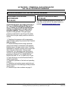
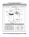
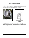
SIGNAGE
A m etal or p lastic i dentification plate s hall b e
permanently mounted to the exterior of the building
at a minimum height of eight (8) feet above grade
directly in line with the exhaust vent terminal for the
horizontally vented gas fueled heating appliance or
equipment. The sign shall read, in print size no less
than one-half (1/2”) inch in size,
“GAS VENT DIRECTLY BELOW. KEEP CLEAR
OF ALL OBSTRUCTIONS.”
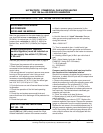
MODELS
Natural
120-150
Propane
120-150
Natural
199-250
Propane
199-250
Natural
300/400/500
Propane
300/400/500
Maximum Gas Supply Pressure
10.5” WC
(2.59kPa)
14.0“WC
( 3.45kPa)
10.5“WC
(2.59kPa)
14.0“WC
( 3.45kPa)
11.0”WC
(2.74kPa)
14.00”WC
(3.49kPa)
Nominal Gas Supply Pressure
7.0”WC
(1.74kPa)
11.0“WC
( 2.74kPa)
7.0“WC
(1.74kPa)
11.0“WC
( 2.74kPa)
7.0”WC
(1.74kPa)
11.0”WC
(2.74kPa)
Minimum Gas Supply Pressure
(Low Gas Press. Switch
Setting)
4.8”WC
(1.20kPa)
8.5“WC
( 2.12kPa)
4.8”WC
(1.20kPa)
8.5“WC
( 2.12kPa)
5.2”WC
(1.54kPa)
11.0“WC
( 2.74kPa)
Manifold Pressure
4.0”WC
(0.98kPa)
10.0“WC
(2.49 kPa)
0“WC
( 0 kPa)
0“WC
( 0 kPa)
4.00“WC
( 1.25kPa)
10.0“WC
( 2.49kPa)