


ULTRAFORCE COMMERCIAL GAS WATER HEATER
SUF 120 thru 400 SERVICE HANDBOOK
State Water Heaters – Technical Training Department 20 Ashland City, Tennessee © 2009
Servicing should only be performed by a Qualified Service Agent 198152-002
CONTROL SEQUENCE (TYPICAL ALL MODELS)
TYPICAL SEQUENCE
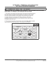
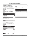
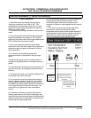
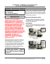
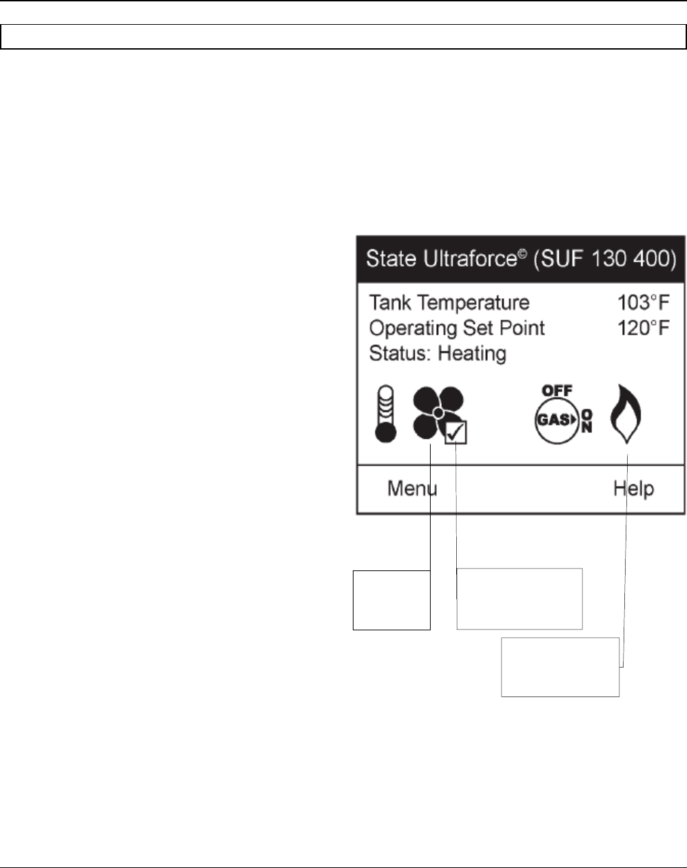
1. When the control is powered it should display
“waiting for connection” and “UIM v2.06”*. The
manufacturer and unit model will be next. The next
display will include water temperature, temperature
setting and heater status.
* This number may change as software revisions are
made.
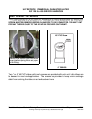
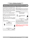
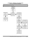
2. The control performed selected system diagnostic
checks immediately upon power up. This includes
confirming the proper state of the air/gas switches and
ECO limit device and powered anodes.
3. If the control determines that the actual water
temperature inside the tank is below the programmed
temperature set-point less the differential, a call for
heat is activated.
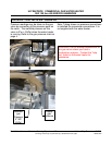
4. If all checks are successfully passed, the
combustion blower is energized for the pre-purge
cycle.
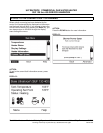
5. When the pre-purge cycle is complete, power is
applied to the igniter element for the igniter warm-up
period.
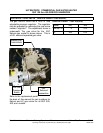
6. At the conclusion of the igniter warm-up period, the
gas valve will open, allowing gas to enter the burner
chamber.
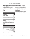
7. The igniter will remain on for a short predetermined
time period, then will be turned off.
8. The control will monitor the flame sense probe to
confirm a flame is present. If a flame is not verified
within predetermined time period, the gas valve will
immediately be closed, and the blower will continue to
run for approximately 30 seconds inter-purge. The
control will try for ignition two more times before
lockout.
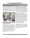
9. If a flame is confirmed, the control will enter the
heating mode where it will continue heating the tank
water until the set point temperature plus differential is
reached. At this point, the gas valve is closed and the
control enters the post-purge cycle.
10. The combustion blower will run for the duration of
the post purge cycle to purge the system of all
combustion gases. When the post purge cycle is
complete, the blower is de-energized and will coast to
a stop.
11. The control will now enter the idle state while
continuing to monitor the internal tank water
temperature and the state of other system devices. If
the temperature drops below the set-point value less
differential, the control will automatically return to
step 2 and repeat the entire operating cycle.
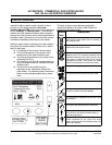
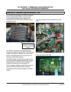
Blow er icon
indicates
power to the
blower
Check mark in the box
indicates the blower
proving sw itch contacts
are made
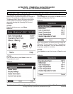
Flame icon indicates
burner is ignited and
that flame has been
sensed.