


5
ELECTRICAL DATA
GENERAL
Check the water heater model and rating plate information against
the characteristics of the branch circuit electrical supply. Do not
connect the heater to an improper source of electricity.
Voltage applied to the water heater should not vary more than +5% to
-10% of the model and rating plate marking for satisfactory operation.
Do NOT energize the branch circuit for any reason before the water
heater tank is lled with water. Doing so may cause the heating
elements to fail.
The installation must conform to these instructions and the local
code authority having jurisdiction. Grounding and electrical wiring
connected to the water heater must also conform to the National
Electrical Code, NFPA 70. This publication is available from The
National Fire Protection Association, 1 Batterymarch Park, Quincy,
MA 02269.
BRANCH CIRCUIT
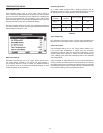
The branch circuit wire size should be established through reference
to the NEC (National Electrical Code) or other locally approved
sources in conjunction with the water heater amperage rating.. Wire
rated at 75°C should be used. For convenience, portions of the wire
size tables from the Code are reproduced in Table 1 on page 9. It
is suggested the electrician size the branch circuit at 125 percent
of the heater rating and further increase wire size as necessary to
compensate for voltage drop in long runs. Voltage drop should not
exceed 3% at the water heater.
HEATER CIRCUITS
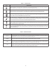
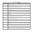
The water heater’s electrical components are pictured and identied
in the Features and Components illustrations in Diagrams 1 and 2.
The model and rating plate provides heater circuit ratings. There are
two main electrical circuits:
Control Circuit: Power supply for the electromagnetic
contactor coils. 120V power is supplied to the contactor coils
by the CCB (Central Control Board) see wiring diagrams in
this manual.
Power Circuit: High voltage, single or three phase, circuit that
carries the heating element load.
The following section and pages describe the water heater circuits
and includes wiring diagrams.
CONTROL CIRCUITS
The water heater is equipped with an electronic control system. The
system includes a CCB (Central Control Board) circuit board, an
immersion temperature probe with ECO for temperature sensing and
limiting, a UIM (User Interface Module) for user interface & information
display and element current sensors for monitoring the power circuits.
Refer to the control circuit label on the water heater for details. The
CCB is powered by a small 120V/24V transformer. The control circuit
operates on 120V supplied by a larger 100VA transformer.
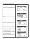
Sequence of Operation
1. When the control is powered, the UIM should display model
information, water temperature, operating setpoint, heating
status and operating mode.
2. If the control determines that the actual water temperature inside
the tank is below the programmed operating setpoint minus the
(1st) differential setpoint, a call for heat is activated.
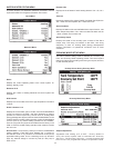
3. After all safety checks are veried the CCB will energize the
contactor coil(s). On models with more than one heating
element the upper most heating elements are energized rst.
Successive heating elements are energized according to
programmed differential setpoints for each heating element.
4. The control remains in the heating mode until the water
temperature reaches the programmed operating setpoint. At
this point the contactors will be de-energized.
5. The control system now enters the standby operating mode
while continuing to monitor the water temperature and the state
of other system devices. If the water temperature drops below
the programmed Operating Setpoint minus the (1st) differential
setpoint, the control will automatically return to step 2 and repeat
the heating cycle.
POWER CIRCUIT
Power circuit wiring is type THHN (or equivalent) rated 600 volts,
105°C, sized as necessary.
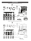
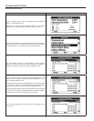
The following wiring diagrams on page 6 are included in this manual
to show typical arrangements of electrical components in the control
and power circuits by voltage and phase characteristics. They are to
be used as a reference by the installer or servicer in performing their
work. An actual diagram of the water heater wiring is furnished with
the water heater.