


14
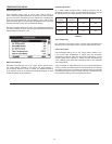
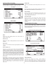
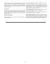
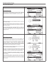
WATER HEATER STATUS MENU
This menu displays non adjustable operational information. Use the
Up & Down Buttons to navigate to the bottom of this menu.
Top of Menu
Bottom of Menu
Status
Displays the current Operating State of the control system. IE:
Heating, Standby, Fault.
Elements On #
Displays the number of heating elements the control system has
energized.
ECO Contact
Displays the current state of the ECO high temperature limit switch
contacts.
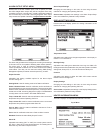
Enable / Disable 1 & 2
Displays the current state, open or closed, of the two Enable/Disable
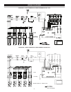
circuits (J7 socket on the CCB - see wiring diagrams on page 6)
provided for external supervisory controls such as building EMS
(Energy Management System). Both of these Enable/Disable circuits
must be closed to “enable” heating operation. If either Enable/Disable
circuit is open for any reason heating operation will be “disabled.”
There is a plug with two jumper wires installed from the factory in the
CCB J7 socket to enable heating operation when external controls
are not in use.
ServiceNote: If a supervisory control(s) is used to enable/disable
heating operation, install eld wiring between the J7 socket on
the CCB and a set of “dry contacts” on the external control per all
applicable building codes. This is a switching circuit only: DO NOT
apply any external voltage or connect any load (IE: relay coil) to
either circuit.
Element # On
Displays the on/off status of each heating element. Yes = On, No =
Off.
Tank Full
Displays the status of the optional LWCO (Low Water Cut Off) device.
Yes = water level is acceptable, No = water level is low.
Alarm Condition
Displays the status of the user denable Alarm Output function - see
Alarm Output Setup Menu. Yes = alarm condition has been met, No
= alarm condition has not been met.
Alarm Relay Output
Displays the state of the normally open contacts of the Alarm
Output relay. This relay (J3 contacts on the CCB - see wiring
diagrams) is used for building EMS (Energy Management
System) notification of operational conditions such as Fault
conditions.
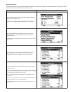
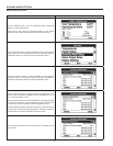
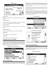
ECONOMY MODE SETUP MENU
This menu contains settings used to establish an “Economy Set
Point” and “Economy Mode” operating periods. This control system
feature can help reduce operating costs during unoccupied, low load,
or peak demand periods.
Desktop Screen During Economy Mode
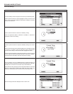
Economy Mode Setup Menu
Setpoint Adjustment
Adjustable user setting (2°F to 50°F - factory default is
20°F) the control system uses to calculate the “Economy
Set Point.” The Economy Set Point = normal Operating Set
Point minus the programmed Setpoint Adjustment value.