


4
• Sensors mounted in the drain pan that turn off the water supply
to the entire home when water is detected in the drain pan.
• Water supply shut-off devices that activate based on the water
pressure differential between the cold water and how water
pipes connected to the water heater.
• Devices that will turn off the gas supply to a gas water heater
while at the same time shutting off its water supply.
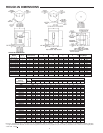
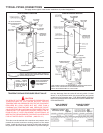
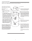
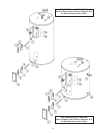
CLEARANCES
A minimum clearance of 4” must be allowed for access to
replaceable parts such as thermostats, drain valve and relief valve.
Adequate clearance for servicing this appliance should be
considered before installation, such as changing the anodes, etc.
FLOOD WARNING
IF THE HEATER BECOMES IMMERSED IN WATER UP TO OR
ABOVE THE LEVEL OF THE BOTTOM OF THE ELEMENT
DOORS, THE HEATER SHOULD BE EXAMINED BY A
COMPETENT SERVICE PERSON BEFORE IT IS PLACED IN
OPERATION.
CHEMICAL VAPOR CORROSION
Water heater corrosion and component failure can be caused by
the heating and breakdown of airborne chemical vapors. Spray
can propellants, cleaning solvents, refrigerator and air conditioning
refrigerants, swimming pool chemicals, calcium and sodium
chloride, waxes, and process chemicals are typical compounds
which are potentially corrosive. These materials are corrosive at
very low concentration levels with little or no odor to reveal their
presence. Products of this sort should not be stored near the
heater.
ELECTRICAL (GENERAL)
Check the heater model and rating plate information against the
characteristics of the branch circuit electrical supply. DO NOT
CONNECT THE HEATER TO AN IMPROPER SOURCE OF
ELECTRICITY. Contact the heater supplier for conversion
information if necessary.
Voltage applied to the heater should not vary more than +5%
to -10% of the model and rating plate marking for satisfactory
operation.
DO NOT ENERGIZE THE BRANCH CIRCUIT FOR ANY REASON
BEFORE THE HEATER TANK IS FILLED WITH WATER.
DOING
SO WILL CAUSE THE HEATING ELEMENTS TO BURN OUT.
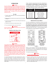
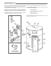
The factory wiring is attached to a terminal block within the external
junction box unit. The branch circuit is connected to the terminal
block within this junction box. The water heater should be
connected to a separate, grounded, branch circuit with overcurrent
protection and disconnect switch. The water heater should be
grounded in accordance with national and local codes.
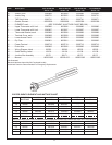
BRANCH CIRCUIT
The branch circuit wire size should be established through
reference to the current edition of NFPA-70, the
National Electrical Code or other locally approved source in
conjunction with the heater amperage rating. For convenience,
portions of the wire size tables from the Code are reproduced
here. The branch circuit should be sized at 125 percent of the
heater rating and further increase wire size as necessary to
compensate for voltage drop in long runs.
CALCULATING
AMPERAGE/OVERCURRENT PROTECTION
The heaters come from the factory in two configurations:
1. Two wire C-2 circuit for single element heater equipped with a
high limit control, single phase power input.
2. Four wire A-8 circuit for dual element heater equipped with
two high limit controls, single phase or three phase power
input.
The heater with dual elements is factory wired for connection to
a three wire, three-phase delta branch circuit, non-simultaneous
operation. In addition a ground conductor is required.
Element connection is for non-simultaneous operation. This
means only one element at a time operates. The wiring diagram,
on page 5, shows the heater may be field converted to
simultaneous element operation by moving the red wire on
“J” terminal to L1. It is then possible for both elements to operate
at once as determined by the thermostats. Regardless of
element connection the heater operates in an “unbalanced”
fashion.
The heater may be field converted to single-phase operation by
moving the wire on L3 of the terminal block to L2. L3 is not used,
see page 5.
The heater, now in single-phase non-simultaneous operation, may
be field-converted to single phase simultaneous operation by
moving the red wire on terminal “J” to L1, see page 5.
This is an example of calculating heater amperage for both types
of element operation. From this, the branch circuit conductor
and overcurrent protection sizing can be established.
The example is of a three-phase 240 volt unit with two, 6 kw
elements. The notations are for units field converted to
single-phase. Check the heater model and rating plate for actual
specifications and substitute those values in the following.
Non-simultaneous: Simultaneous:
(as factory wired) (Field conversion)
3000 : 240 = 12.5 amps* 3000 : 240 = 12.5 amps*
12.5 x 1.73 = 21.6 amps
*NOTE: as a single-phase *NOTE: as a single-phase
non-simultaneous unit. simultaneous unit the
total is:
12.5 x 2 = 25 amps
The rating of the overcurrent protection should be computed on
the basis of 125 percent of the total connected load amperage.
Where the standard ratings and settings do not correspond with
this computation, the next higher standard rating or setting should
be selected.
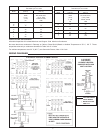
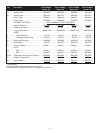
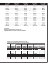
Portion of Table 310-16 (NFPA-70) follows:
Allowable Ampacities of Insulated Copper Conductors. Not more
than three conductors in Raceway or Cable or Direct Burial (Based
on Ambient Temperature of 30° C, 86° F).
These ampacities relate only to conductors described in Table
310-13 in Code.
For ambient temperatures over 30° C (86° F), see Correction
Factors, Note 13 in Code.