


22 305, 505, 705 Indoor Manual
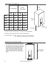
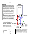
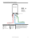
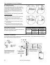
• Vertical terminations must incorporate a condensate
drain and trap as close as possible to the appliance.
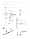
• Slope any horizontal venting 1/4 inch per foot (19
mm / m), towards the heater if the condensate
collector is used, or towards the exhaust terminal if
the condensate collector is not used.
• Dispose of condensate per local codes.
• The condensate trap must contain a minimum of 3
inches (75 mm) of water.
• This water heater has an integrated condensate
collector.
• Regions of cold climate will create more condensate
in the vent system. The condensate collector
should be used in cold climates.
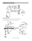
Venting Instructions
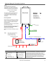
Condensate
Condensate formation can occur in high efficiency
direct vent appliances. To prevent condensate
damage follow these instructions.
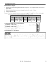
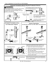
Intake / Exhaust Guidelines
Refer to the specific instructions on your vent product for additional installation requirements.
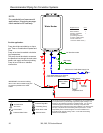
NOTICE
Provisions must be made to prevent the condensate
from entering the water heater. Without proper
drainage or disposal, condensate will damage the heat
exchanger.
WARNING
If the condensate collector is not used, the drain pipe
must be capped to prevent exhaust gases and
condensate from entering the building. The cap is
supplied on the appliance.
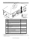
• This water heater is a direct vent water heater and
therefore is certified and listed with the vent
system. You must use vent components that are
certified and listed with the water heater model.
• Do not combine vent components from different
manufacturers.
• The vent system must vent directly to the outside
of the building and use outside air for combustion.
• Venting should be as direct as possible with a
minimum number of pipe fittings.
• Avoid dips or sags in horizontal vent runs by
installing supports per the vent manufacturer’s
instructions.
• Support horizontal vent runs every four feet and all
vertical vent runs every six feet or in accordance
with local codes.
• Vent diameter must not be reduced.
• Do not connect the venting system with an existing
vent or chimney.
• Do not common vent with the vent pipe of any
other water heater or appliance.
• Vent connections must be firmly pressed together
so that the gaskets form an air tight seal.
• On the 305 and 505 models, the vent piece
connected to the water heater must be secured
with one self-tapping screw.
• Refer to the instructions of the vent system
manufacturer for component assembly instructions.
• If the vent system is to be enclosed, it is suggested
that the design of the enclosure shall permit
inspection of the vent system. The design of such
enclosure shall be deemed acceptable by the
installer or the local inspector.
NOTICE
If it becomes necessary to access an enclosed vent
system for service or repairs, the manufacturer is not
responsible for any costs or difficulties in accessing
the vent system. Warranty does not cover obtaining
access to an enclosed vent system.