


14 305, 505, 705 Indoor Manual
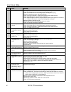
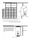
Clearances from Appliance
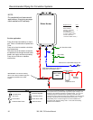
1. Identify the installation location and confirm that
the installation will meet all required clearances.
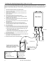
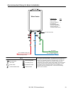
2. Securely attach the water heater to the wall using
any of the holes in the wall installation brackets
which are at the top and bottom of the water
heater. Ensure that the attachment strength is
sufficient to support the weight. Refer to the
weight of the water heater in the Specifications
section.
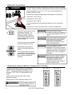
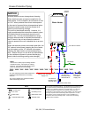
Attachment of the Water Heater
wall installation
brackets
to side
to front
to top
to floor/ground
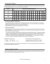
to Combustibles
to Non-
Combustibles
305
505
705
305
505
705
Top of
Heater
6 inches
(152 mm)
12 inches
(305 mm)
2 inches
(51 mm)
2 inches
(51 mm)
Back of
Heater
0 (zero) 0 (zero) 0 (zero) 0 (zero)
Front of
Heater
6 inches
(152 mm)
24 inches
(610 mm)
6 inches
(152 mm)
24 inches
(610 mm)
Sides of
Heater
2 inches
(51 mm)
2 inches
(51 mm)
1/2 inch
(13 mm)
1/2 inch
(13 mm)
Floor/
Ground
12 inches
(305 mm)
12 inches
(305 mm)
12 inches
(305 mm)
2 inches
(51 mm)
Vent
0 (zero) 4 inches * 0 (zero) 0 (zero)
* 4 inches (102 mm) for enclosed area; 1 inch (26 mm) for unenclosed area.
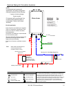
The clearance for servicing is 24 inches in front of the water heater.
For closet installation: 305, 505: clearance is 6 inches (152 mm) from the front.
705: clearance is 24 inches (610 mm) from the front.