


3
3
WARNING
Never operate the electrical heating element without being
certain the tank is completely filled with water. If any air is left in
the top of the tank, the heating element will burn out.
LOCAL CODES
The installation of the tank must be in accordance with these
instructions and all applicable local codes and electric utility
requirements. In the absence of local codes, install in accordance
with the latest edition of the National Electrical Code (NFPA-70).
TEMPERATURE-PRESSURE
RELIEF VALVE
WARNING
For protection against excessive pressures and temperatures
in this water heater, install temperature-pressure protective
equipment required by local codes, but not less than a
combination temperature-pressure relief valve certified by a
nationally recognized testing laboratory that maintains periodic
inspection of production of listed equipment or materials, as
meeting the requirements for Relief Valves and Automatic Gas
Shut-off Devices for Hot Water Supply Systems, the latest edition
of ANSI Z21.22. This valve must be marked with a maximum
set pressure not to exceed the marked hydrostatic working
pressure of the water heater (150 lbs./sq. in.).
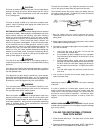
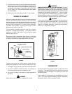
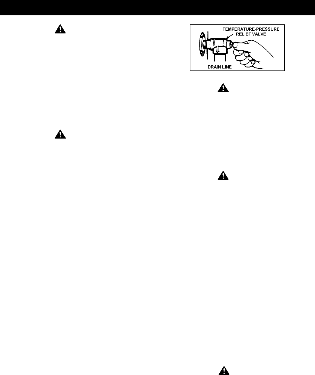
Install the temperature-pressure relief valve directly into the fitting
of the water heater. Position the valve downward and provide
tubing so that any discharge will exit only within 6 inches above,
or at any distance below the structural floor. Be certain that no
contact is made with any live electrical part. The discharge
opening must not be blocked or reduced in size under any
circumstances. Excessive length, over 15 feet, or use of more
than two elbows can cause restriction and reduce the discharge
capacity of the valve.
No valve or other obstruction is to be placed between the relief
valve and the tank. Do not connect tubing directly to discharge
drain unless a 6” air gap is provided. To prevent bodily injury,
hazard to life or damage to property, the relief valve must be
allowed to discharge water in quantities should circumstances
demand. If the discharge pipe is not connected to a drain or
other suitable means, the water flow may cause property damage.
The Discharge Pipe:
• Must not be smaller in size than the outlet pipe size of the
valve, or have any reducing couplings or other restrictions.
• Must not be plugged or blocked.
• Must be of material listed for hot water distribution.
• Must be installed so as to allow complete drainage of both
the temperature-pressure relief valve, and the discharge
pipe.
• Must terminate at an adequate drain.
• Must not have any valve between the relief valve and tank.
When installing the temperature-pressure relief valve, use two
or three turns of teflon tape or other suitable thread sealer around
the threaded end of the valve.
FIGURE 2
WARNING
The temperature-pressure relief valve should be manually
opened once a year. Caution should be taken to ensure that
(1) no one is in front of or around the outlet of the temperature-
pressure relief valve discharge line, and (2) the water manually
discharged will not cause any bodily injury or property damage
because the water may be extremely hot.
If after manually operating the valve, it fails to completely
reset and continues to release water, immediately close the
cold water inlet to the water heater, follow the draining
instructions, and replace the temperature-pressure relief
valve with a new one.
WARNING
If the temperature-pressure relief valve on the appliance
weeps this may be due to thermal expansion. The water
supply serving this tank may have a check valve installed.
Contact the water supplier or local plumbing contractor on
how to control this situation. Do not plug the temperature-
pressure relief valve.
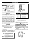
LOCATING THE GEOTHERMAL STORAGE TANK
If you have a choice of where to install the tank, these ideas may
help you decide.
1. Put the tank indoors as close as possible to where you use
the most hot water. This tank is not intended for outdoor
installation.
2. It is handy to have a floor drain, tub or sink nearby. That will
make it easy to drain water from the tank. It is also a good
place to end the drain line of the temperature-pressure relief
(T & P) valve.
3. The tank or the pipes and the connections may, in time, leak.
Put the tank in a place where a water leak will not damage
anything.
4. You must not put the tank in an area where it might freeze.
You must turn off the electricity to the tank before you drain it,
to protect the heating elements.
5. Make sure that you are able to reach the drain valve and all
access panels when the tank is in place. This will make it
easy to service the tank.
6. The tank must be level before you begin the piping.
CAUTION
WATER HEATERS EVENTUALLY LEAK. The installation of the
tank must be accomplished in such a manner that if the tank or
any connections should leak, the flow of water will not cause
damage to the area adjoining the water heater or to lower floors
of the structure. When such locations can’t be avoided, a suitable
drain pan should be installed under the tank. Such a pan should
be no greater than 1 1/2 inches deep, have a minimum length
and width of at least two inches greater than the tank
dimensions and must be piped to an adequate drain.
INSTALLATION