


9
The valve is certified by a nationally recognized testing laboratory that
maintains periodic inspection of production of listed equipment of
materials as meeting the requirements for Relief Valves and Automatic
Gas Shut-off Devices for Hot Water Supply Systems, ANSI Z21.22 •
CSA 4.4, and the code requirements of ASME.
If replaced, the valve must meet the requirements of local codes, but
not less than a combination temperature and pressure relief valve
certified as indicated in the above paragraph.
The valve must be marked with a maximum set pressure not to exceed
the marked hydrostatic working pressure of the water heater
(150 psi = 1,035 kPa) and a discharge capacity not less than the water
heater input rate as shown on the model rating plate.
For safe operation of the water heater, the relief valve must not be
removed from its designated opening nor plugged.
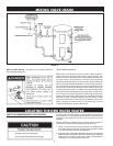
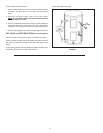
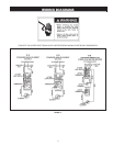
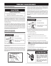
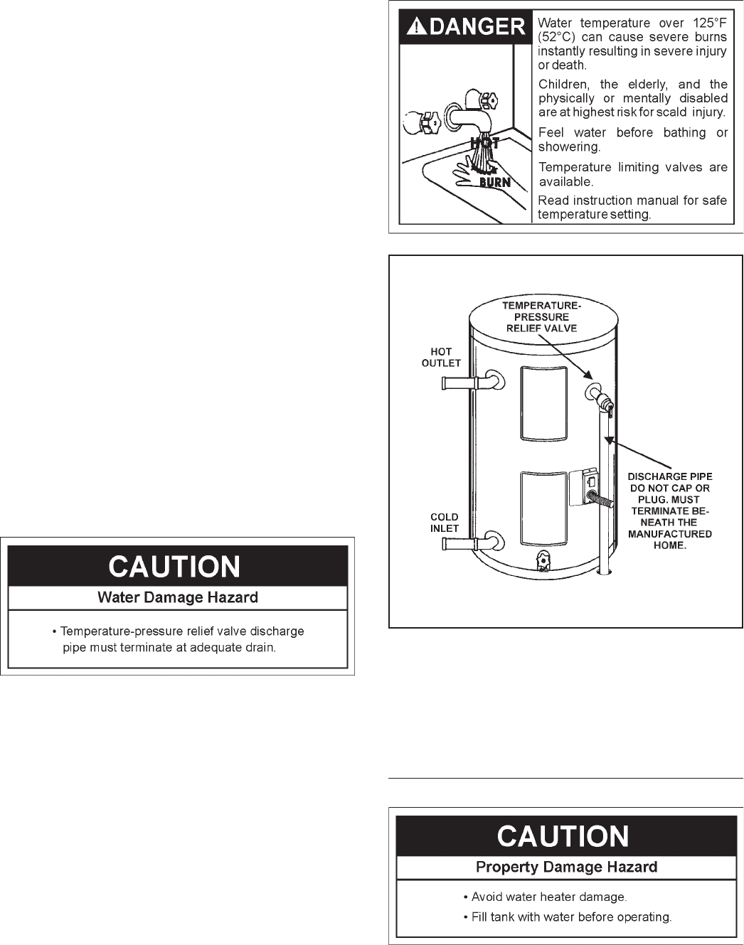
The temperature-pressure relief valve must be installed directly into
the fitting of the water heater designed for the relief valve. Position the
valve downward and provide tubing so that any discharge will exit
only within 6 inches (153 mm) above, or at any distance below the
structural floor. Be certain that no contact is made with any live electrical
part. The discharge opening must not be blocked or reduced in size
under any circumstances. Excessive length, over 30 feet (9.14 m), or
use of more than four elbows can cause restriction and reduce the
discharge capacity of the valve.
No valve or other obstruction is to be placed between the relief valve
and the tank. Do not connect tubing directly to discharge drain unless
a 6 inch air gap is provided. To prevent bodily injury, hazard to life, or
property damage, the relief valve must be allowed to discharge water
in quantities should circumstances demand. If the discharge pipe is not
connected to a drain or other suitable means, the water flow may
cause property damage.
The Discharge Pipe:
• Shall not be smaller in size than the outlet pipe size of the valve, or
have any reducing couplings or other restrictions.
• Shall not be plugged or blocked.
• Shall be of material listed for hot water distribution.
• Shall be installed so as to allow complete drainage of both the
temperature-pressure relief valve, and the discharge pipe.
• Shall terminate beneath the manufactured home.
• Shall not have any valve between the relief valve and tank.
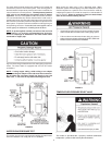
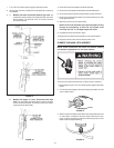
The temperature-pressure relief valve must be manually operated at
least once a year. Caution should be taken to ensure that (1) no one is
in front of or around the outlet of the temperature-pressure relief valve
discharge line, and (2) the water manually discharged will not cause
any bodily injury or property damage because the water may be
extremely hot.
FIGURE 5.
If after manually operating the valve, it fails to completely reset and
continues to release water, immediately close the cold water inlet to
the water heater, follow the draining instructions, and replace the
temperature-pressure relief valve with a new one.
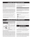
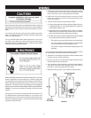
FILLING THE WATER HEATER
Never use this water heater unless it is completely full of water. To
prevent damage to the tank, the tank must be filled with water. Water
must flow from the hot water faucet before turning “ON” electrical
supply to the water heater.