


51
8640
0702
8320
1540
8320
0702
1430
1440
1460
1450
8620
8620
1400
1440
1490
1570
8610
A.0500.551 – IM-TGMAG/02.00 EN (02/2008)
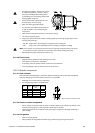
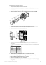
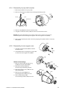
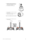
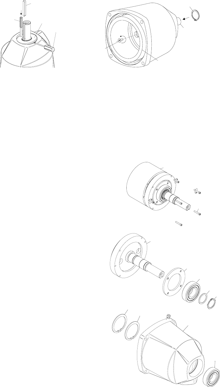
4.2.4 Disassembly of pump shaft complete
1. Remove key (1570) from the pump shaft.
2. Remove sealing segment (1490) from the bearing bracket (see picture).
3. Remove circlip (8640) from the rear end of the shaft.
4. Un-tighten countersunk screws (1540) from the front end and remove them.
Remark: The pump shaft (0702) can be rotated to allow access to these screws. Be care-
ful that the spanner does not damage the magnets in the outer magnectic rotor (8320).
5. Drive out the complete pump shaft to the front by tapping with a plastic hammer on the pump
shaft (0702).
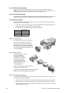
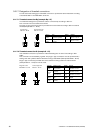
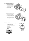
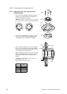
4.2.5 Disassembly of outer magnetic rotor
1. Un-tighten cap head screws (8610) crosswise
and remove them.
2. Use threaded holes in the flange of the pump shaft
to remove the outer magnetic rotor (8320).
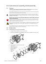
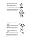
Removal of ball bearings
1. Remove circlips (1450) and support ring
(1460) from the pump shaft (0702).
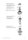
2. Remove the bearing (1440) from
the shaft using a ball-bearing extractor.
3. Remove the bearing cover (1430) from the
pump shaft (0702).
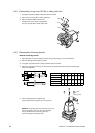
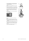
4. Remove both circlips (8620) from
the bearing bracket (1400) to the front.
5. Drive out ball bearing (1440)
from the bearing bracket (1400) to the rear.
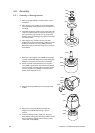
Screw driver
Piercer