


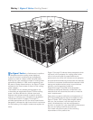

Marley
/
Sigma F Series Cooling Tower
/
Engineering Data : Support
5
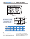
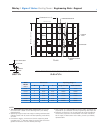
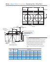
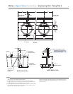
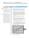
A
SPACES AT 4'-0" =
L
W
OVERALL OF BASIN
SUMP
OVERFLOW
MAKEUP
VALVE
INTERMEDIATE BEAM
AIR INLET FACE
AIR INLET FACE
CASED ENDWALL FACE
CASED ENDWALL FACE
PRIMARY SUPPORT
BEAM
PLAN
ELEVATION
NOTE
1 Use this bulletin for preliminary layouts only. Do not use
for construction. Obtain current drawings from your Marley
representative.
2 Operating weight is total wet weight including stainless steel
collection basin with 6" (recommended operating water level)
of water.
3 Purchaser to design, construct and furnish supporting steel
complete with
13
⁄16" diameter holes for anchor bolts to suit the
general dimensions of current Marley drawings.
4 Last number of model indicates number of cells. Change as ap-
propriate for your selection. Primary engineering data is per cell.
5 Maintain no less than 2'-0" of clear space at tower endwalls for
construction purposes. Louvered faces must have unobstruct-
ed air supply. If obstructions exist nearby, consult your Marley
representative.
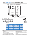
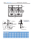
2
1
/4" MAX.
NORMAL
GAGE
COL. & ANCH. BOLT
C
L
SECTION
Tower
Model
Note 4
Dimensions Operating Weight lb
A W L Single Fan Cell Each Cell Add
F1211 4 26'-6" 16'-0" 55810 51510
F1221 4 28'-6" 16'-0" 59300 54920
F1231 5 28'-6" 20'-0" 70180 65760
F1241 6 28'-6" 24'-0" 81410 77020
F1251 6 32'-6" 24'-0" 91070 86450
F1261 7 32'-6" 28'-0" 102800 98090