


7
/ Installation /
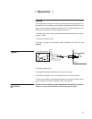
Temperature / Water Level Sensor Assembly
This basin heater package is equipped with a combination tempera-
ture/liquid level sensor and may have a thermal cutoff switch. Both
are safety devices that must not be altered or changed in any man-
ner. Disabling either safety feature may result in combustion and/
or fire, which could cause damage or destroy the tower and may
cause damage to persons or property nearby. Failure of one or both
safety devices requires that the control panel be de-energize and
tag circuit out for maintenance. Do not re-energize the unit until all
safety devices are fully operational in accordance with manufacturer's
specifications.
The sensor assembly is factory installed to the control panel. Do not at-
tempt to lengthen or shorten the cord. Sensor assemblies with various
lengths up to 99'-0" are available and may be specified at the time of
purchase for additional cost.
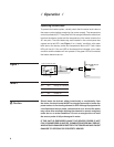
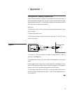
Install the sensor probe in the cold water basin at least 1" above the high-
est point of the heater element and at least 6" away from the heater. The
probe should be installed in the coldest part of the basin for maximum
protection. It should extend into the open basin a minimum of 4". A
1
⁄2" NPT
PVC bulkhead fitting is provided on the sensor for mounting through the
basin wall. Provide an 1
5
⁄8" clearance hole through the basin wall. Remove
the nut from the bulkhead fitting and insert the sensor probe through the
hole. Hand tighten the mounting nut onto the fitting, holding the bulkhead
fitting to avoid twisting the cord. Lightly tighten the nut.
Warning