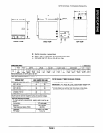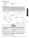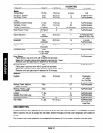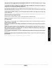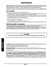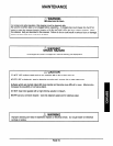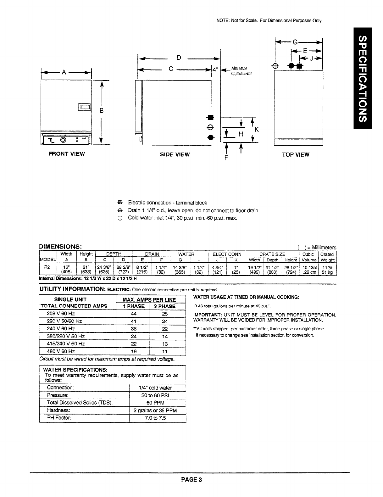
NOTE: Not for Scale. For Dimensional Purposes Only.
k-G-
FRONT VIEW
+-D-
-c
4
SIDE VIEW
rc- MINIMUM
CLEARANCE
F
TOP VIEW
%%
Electric connection - terminal block
6&
Drain 1 l/4” o.d., leave open, do not connect to floor drain
5
Cold water inlet l/4”, 30 p.s.i. min.-60 p.s.i. max.
DIMENSIONS:
( ) = Millimeters
Width
Height
DEPTH
DRAIN WATER / ELECTCONN /
CRATE SIZE
Cubic Crated
MODEL A
B C D
E i F
G
H J K
I Width 1 Depth 1
Height
Volume Weight
R2 - ”
$6,
(:;3) (625)
24318” 28318” 8 l/2* / 1 114”
14 318”
1 l/4” 4 314”
(727) (216) ! (32) (365)
(32)
(121)
(2)
19 l/2” ’ 31 i/2- ’ 28 l/2” 10.13cf
112::
(499) / (800) 1 (724) .29 cm 51 kg
Internal Dimensions: 13 11’2 W x 22 D x 12 l/2 H
UTILITY INFORMATION:
ELECTRIC: One electric connection per unit is required.
SINGLE UNiT
MAX. AMPS PER LINE
TOTAL CONNECTED
AMPS
1 PHASE / 3
PHASE
208 V 60 Hz
44 I
25
220 V 50160 Hz
41
24
240 V 60 Hz
38
22
3BOl220 V 50 Hz
24
14
1
4151240 V 50 Hz I 22 I 13 I
1 480V60Hz
19 11
J
Circuit must be wired for maximum amps at required voltage.
! WATER SPECIFICATIONS:
To meet warranty requirements, supply water must be as
follows:
Connection:
l/4”
cold water
Pressure: 30 to 60 PSI
Total Dissolved Solids TTDS):
60 PPM
1 Hardness:
1 2 arainsor35 PPM
1
1 PH Factor:
I
7.0 to 7.5
I
WATER USAGE AT TIMED OR MANUAL COOKING:
0.46 total gallons per minute at 45 p.s.i.
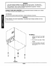
IMPORTANT:
UNIT MUST
BE LEVEL FOR PROPER OPERATION.
WARRANTY WILL BE VOIDED FOR IMPROPER INSTALLATION.
“Ail
units shipped per
customer order, three phase or single phase.
If necessary to change see installation section for conversion.
PAGE 3


