


Instructions for the installer
31
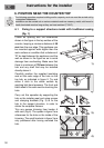
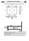
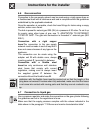
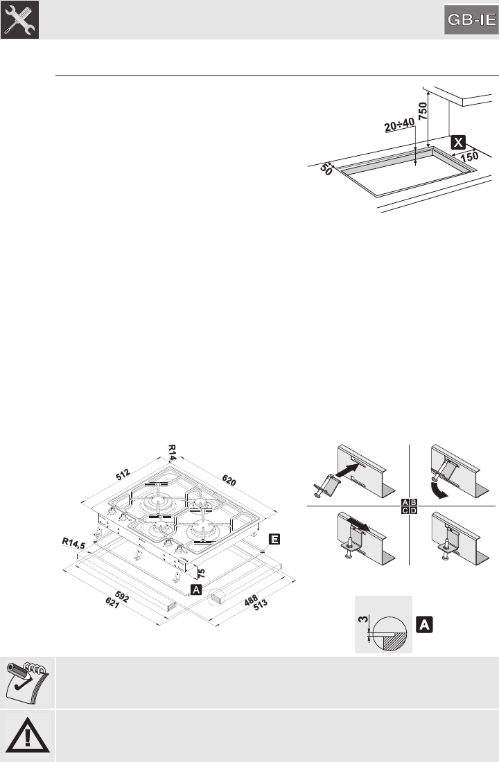
6.2 Fixing to the electric model support structure
Create an opening with the dimensions
shown in the figure in the top surface of the
counter, keeping a minimum distance of 50
mm from the rear edge.
The lower part of the casing must be fully
accessible after the appliance has been
installed. This appliance can be mounted
against walls higher than the work surface
on condition that a distance of "X" be kept
between the appliance and the wall as
shown in the figure so as to avoid damage
from overheating.
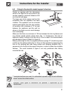
1)
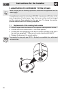
Make sure that there is a minimum of 750 mm between the hob ring flames and
any shelves placed directly above them (Fig. 1). Furthermore, this kind of
appliance needs a milling on the hob top of 3 mm in depth; the measurements
are indicated in figure 4 (detail A of figure 2).
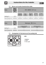
Before positioning the hob, the supplied adhesive sponge “E” should be spread
out flat over the milling surface (fig. 2). Carry out this operation by supporting the
hob on the isolating seal and using screws and clamping brackets (Fig. 3
sequence) to fix the hob to the support structure, in order to obtain the complete
flatness. The small brackets in figure 3 are only positioned after having
mounted the hob.
2)
3)
4)
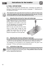
If laminated surfaces are used, it is advisable to spread a layer of anti-infiltration
“primer” across the milled surface.
Important: Other types of installation are possible if supervised by the
manufacturer!