


Page: 4
1.4.8 TRANSMITTER ELECTRONICS
Electronic Assembly consist of one top transmitter board (connected to the cover plate) and on lower
interface board. Connectors for wiring for power, signal interface and alarm relays are located on the
interface board assembly
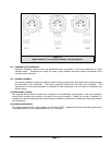
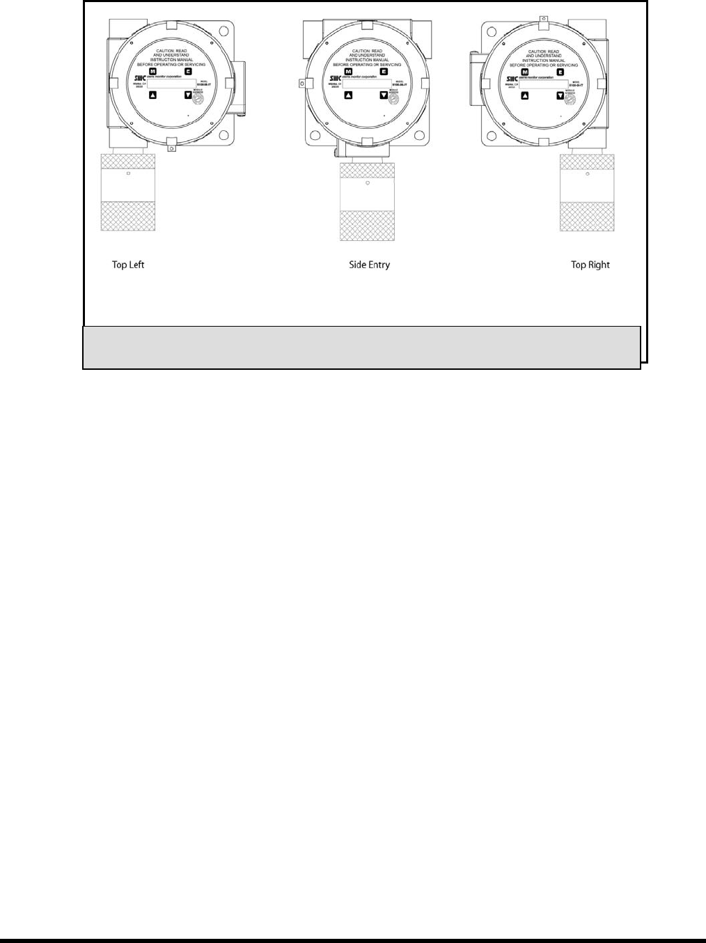
1.4.9 SENSOR ASSEMBLY
The sensor assembly includes an explosion proof housing containing the gas sensor and a wiring harness
for connection to the transmitter. The sensor assembly threads into one hub of the enclosure. The
exposed end of the sensor assembly is threaded to allow connection of a rain-shield or calibration gas
delivery fitting.
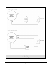
1.5 INTERCONNECT WIRING
Not supplied with the sensor module, but necessary to the installation and operation is the multi conductor
wiring which connects the module to its power source and controller. Before this wiring is installed it is
important to read and understand the control system installation instructions to determine wiring requirements
and alternatives.
1.6 POWER REQUIREMENTS
IT modules operate on DC power between 10 VDC and 30 VDC. Regulated DC power must be supplied from
a separate source, or from an approved Sentry or IT controller.
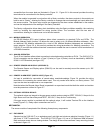
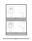
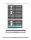
Figure 1-3
Model 5100-XX-IT Toxic Gas Sensor Module – Mounting Options