


Page: 2
accessible from the cover plate as illustrated in Figure 3-1. Figure 3-6 in this manual provides the wiring
terminations for connections to the Sentry controller.
When the module is operated in conjunction with a Sentry controller, the alarms outputs in the module can
both be set to “Sentry”, allowing the Sentry controller to manage alarm acknowledge and reset rather than
the sensor module. The alarm relay outputs are triggered by the alarm values established in the module,
and can be independent of the settings in the Sentry controller.
The Sentry configuration allows daisy chain installation using the Sentry multiplex capability, thus reducing
costs by avoiding the requirement for wiring junction boxes. The connector card has two sets of
connections, allowing for a continuous run to the next module.
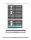
1.4.2 MODBUS OPERATION
An RS-485 Modbus RTU serial interface allows direct connection to standard PLCs and DCSs. The
Module Address Switch (section 3.5) allows the user to select up to 16 different Modbus addresses. Also,
an additional 238 Modbus addresses (for a total of 254 different Modbus Addresses) are available via
menu selection. Figure 3-6 in this manual provides the wiring terminations for Modbus connections. The
5100-XX-IT provides the additional terminal connectors to enable the user to connect In/Out terminations of
a RS-485 connection.
1.4.3 ANALOG OPERATION
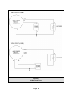
The 4-20 mA interface allows direct connection to standard analog controllers or PLCs. The 5100-XX-IT 4-
20 mA connection can be wired as a Type 3 (3-wire) or Type 4 (4-wire) circuit as described by ANSI/ISA-
50.00.01-1975 Standard (see figure 3-5).
1.4.4 REMOTE SENSOR AND DISPLAY (APPENDIX D)
The Remote Sensor and Display option (5394-52) can be used to remotely mount the sensor up to 100’
from the transmitter.
1.4.5 REMOTE ALARM RESET (DIGITAL INPUT) (Figure 3-7)
An input is available for connection of remote alarm reset/acknowledge. Figure 3-4 provides the wiring
termination for connecting the remote alarm reset. This only resets local alarms, not Sentry alarms. This
input can be wired as supervised or non-supervised.
Note that when the Remote Alarm Reset is operated in a supervised mode that both the switch and resistor
must be present as outlined in Figure 3-7.
1.4.6 OPTIONAL INTEGRAL RELAYS
The optional relays are integral to the gas sensor module and are rated as SPDT, 250VAC, 8 Amps for the
High Alarm and Low Alarm relays and SPDT, 250 VAC, 2 Amp for the Trouble relay.
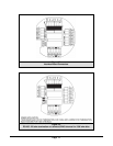
If the gas sensor module is provided with the optional relays, it will include Terminal P4 on the interface
board (Figure 3-2). Relay output connections are on P4.
MECHANICAL
The sensor module of comprised of the following three primary components:
1.4.7 ENCLOSURE
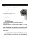
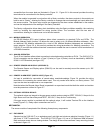
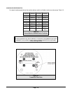
Standard on the 5100-XX-IT is an explosion-proof, rain-tight cast aluminum electrical housing (Figure 1-1)
with three ¾” FNPT conduit hubs. The 5100-XX-IT-SS (Figure 1-2) has a 316 Stainless Steel enclosure.
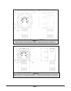
Both enclosure covers have a viewing window. The design of the enclosure allows 3-way mounting choices
as shown in figure 1-3.